


Lenze · 8400 HighLine · Reference manual · DMS 12.0 EN · 06/2017 · TD23
1340
17
Function library
17.1
Function blocks | L_Curve_3
_ _ _ _ _ _ _ _ _ _ _ _ _ _ _ _ _ _ _ _ _ _ _ _ _ _ _ _ _ _ _ _ _ _ _ _ _ _ _ _ _ _ _ _ _ _ _ _ _ _ _ _ _ _ _ _ _ _ _ _ _ _ _ _
17.1.69.1 Use of the L_Curve_3 for tensile force characteristic
In case of centre winders, the drive torque is transmitted from the centre via the individual layers
up to the winder surface. In case of smooth materials and high diameter areas, it is mostly required
to reduce the tensile force depending on the diameter.
The FB
L_Curve_3
can be used to generate a tensile force profile depending on the diameter. For this
purpose, the selection "4: Out = f(characteristic)" has to be set in
.
The characteristic is marked by an initial range with constant evaluation (100 %) and a second range
where the tensile force is adapted to the diameter.
The part of the characteristic that depends on the diameter can be generated for a linear tensile
force profile, a linear torque profile or based on a specified characteristic. The respective selection is
Linear tensile force profile
•
nD0_a
serves to define at which diameter the tensile force decrease is to start.
(from V12.00.00)
Selection of the tensile force profile
Use of the L_Curve_3 for tensile
0 Linear tensile force profile
Lenze setting
1 Linear torque profile
2 Tensile force profile according to
characteristic
Parameters
Possible settings
Info
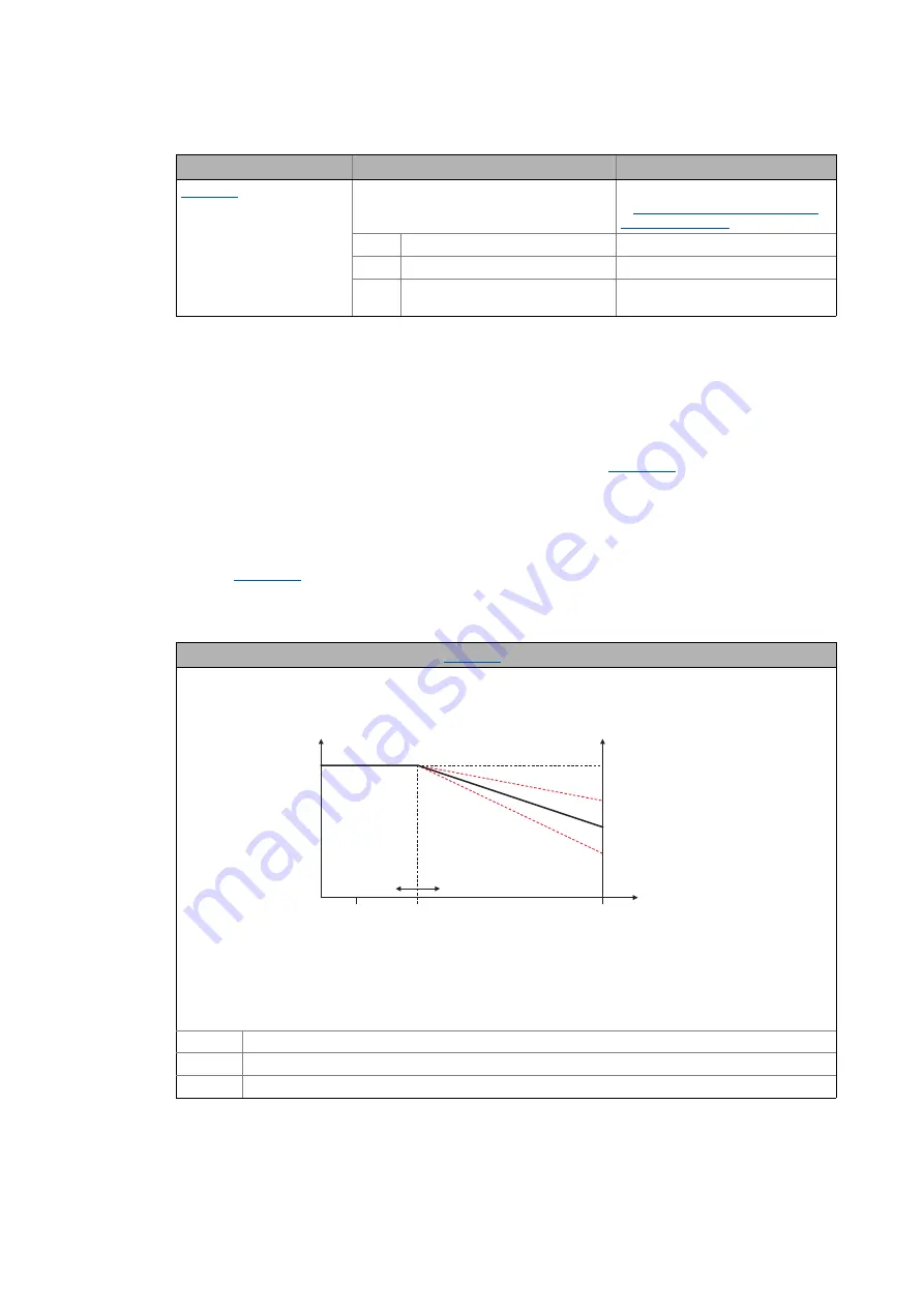
Characteristic for a linear tensile force profile (
= 1)
Characteristic
Tensile force
Diameter
Function for D > D0:
D Current diameter (
nDiameter_a
)
D0 Initial point for diameter dependency (
nD0_a
)
HW Tensile force valuation (
nCurveCtrl_a
)
DMin
(DMax)
100 %
D0
0 %
100 %
HW
100 %
nCurveCtrl_a = 50 %
100 %
D D0
–
100 % D0
–
-----------------------------
–
100 % HW
–
(
)
⋅