


Lenze · 8400 HighLine · Reference manual · DMS 12.0 EN · 06/2017 · TD23
1219
16
Working with the FB Editor
16.4
Reconfiguring the predefined interconnection
_ _ _ _ _ _ _ _ _ _ _ _ _ _ _ _ _ _ _ _ _ _ _ _ _ _ _ _ _ _ _ _ _ _ _ _ _ _ _ _ _ _ _ _ _ _ _ _ _ _ _ _ _ _ _ _ _ _ _ _ _ _ _ _
16.4.1.4
Inserting a comment
Comments can be inserted at any position in the drawing area.
As of the »Engineer« V2.10
, the interior colour and text alignment of a comment can be changed via
a properties dialog. Now the sizes of comments can also be changed using the mouse pointer. When
using different interior colours you can use comments to graphically arrange areas that belong
together in terms of function or separate them from other areas:
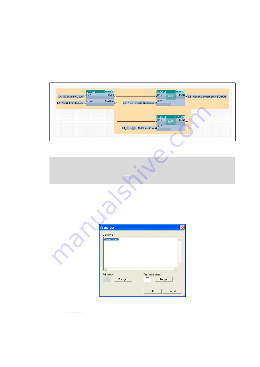
[16-7] Example: Graphical arrangement of FBs by means of two comments that overlap.
How to insert a new comment into the interconnection:
1. Move the mouse pointer to the (free) position in the drawing area where the comment is
to be inserted.
2. Go to the
Context menu
(right mouse key) and select the
New comment
command.
• The
Properties
dialog box is displayed:
3. Enter the required comment into the text field.
4. Optional: Change preset interior colour.
• For this purpose, click the left
Change...
button to open the
Colour
dialog box to select
another interior colour.
Note!
The term "Arrangement" does not mean a logical arrangement of the function blocks.
The comments are only graphical presentation elements of the FB Editor.