278
D90
PLUS
LINE DISTANCE PROTECTION SYSTEM – INSTRUCTION MANUAL
GROUPED PROTECTION ELEMENTS
CHAPTER 7: PROTECTION
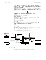
In the UR
Plus
-series devices, which use a Fourier transform, the calculated current
magnitude will ramp-down to zero one power frequency cycle after the current is
interrupted, and this lag should be included in the overall margin duration, as it occurs
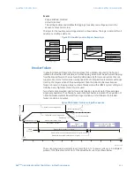
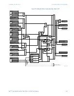
after current interruption. The breaker failure main path sequence diagram shows a
margin of two cycles; this interval is considered the minimum appropriate for most
applications.
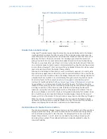
In bulk oil circuit breakers, the interrupting time for currents less than 25% of the
interrupting rating can be significantly longer than the normal interrupting time.
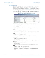
Use Timer 3
Range: Yes, No
Default: Yes
If this setting value is “Yes”, the slow path is operational.
Timer 3 Pickup Delay
Range: 0.000 to 65.535 seconds in steps of 0.001
Default: 0 seconds
Timer 3 is set to the same interval as timer 2, plus an increased safety margin. Because
this path is intended to operate only for low level faults, the delay can be in the order of
300 to 500 ms.
Breaker Position 1 Phase A/3P
Range: any FlexLogic™ operand or shared operand
Default: Off
This setting selects the operand that represents the protected breaker early-type
auxiliary switch contact (52/a). When using the single-pole breaker failure scheme, this
operand represents the protected breaker early-type auxiliary switch contact on pole A.
This is normally a non-multiplied form-A contact. The contact may even be adjusted to
have the shortest possible operating time.
Breaker Position 2 Phase A/3P
Range: any FlexLogic™ operand or shared operand
Default: Off
This setting selects the operand that represents the breaker normal-type auxiliary switch
contact (52/a). When using the single-pole breaker failure scheme, this operand
represents the protected breaker auxiliary switch contact on pole A. This may be a
multiplied contact.
Breaker Test On
Range: any FlexLogic™ operand or shared operand
Default: Off
This setting selects the operand that represents the breaker in-service/out-of-service
switch set to the out-of-service position.
Phase Current High-Set Pickup
Range: 0.001 to 30.000 pu in steps of 0.001
Default: 1.050 pu
This setting specifies the phase current output supervision level. Generally, this setting
should detect the lowest expected fault current on the protected breaker, before a
breaker opening resistor is inserted.

