506
D90
PLUS
LINE DISTANCE PROTECTION SYSTEM – INSTRUCTION MANUAL
FAULT REPORT
CHAPTER 10: DIGITAL FAULT RECORDER
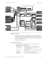
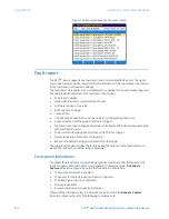
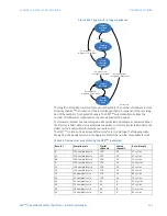
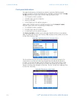
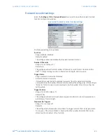
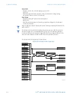
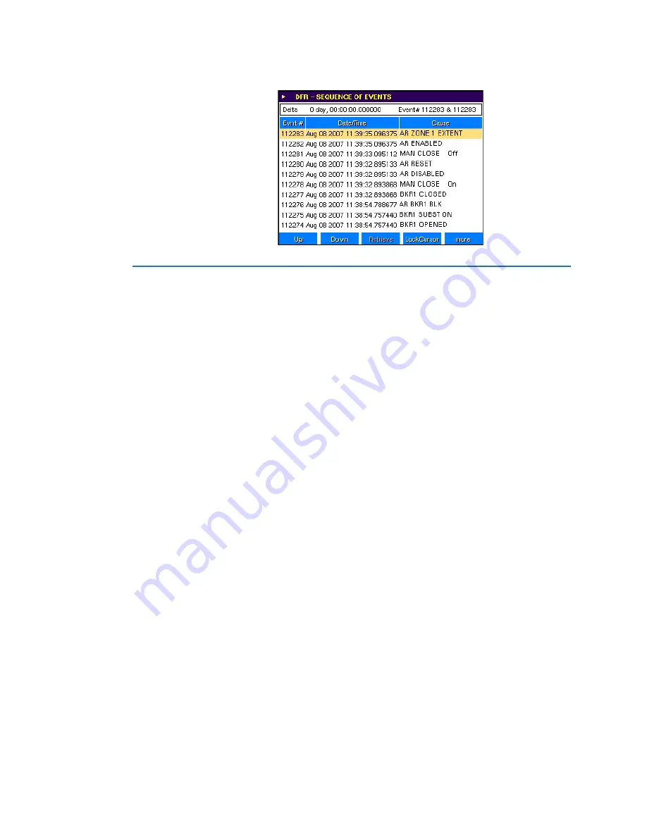
Figure 435: Example sequence of events record
Fault report
The D90
Plus
device supports one fault report and an associated fault locator. The signal
source and trigger condition, as well as the characteristics of the line or feeder, are entered
in the fault report configuration settings.
The fault report stores data, in non-volatile memory, pertinent to an event when triggered.
The captured data contained in the fault report file includes:
•
Fault report number.
•
Device identification, programmed by the user.
•
Firmware revision of the relay.
•
Date and time of trigger.
•
Cause of trip.
•
Line and feeder identification via the name of a configured signal source.
•
Active protection setting group at the time of trigger.
•
Pre-fault current and voltage phasors (two cycles before 50DD disturbance associated
with fault report source).
•
Fault current and voltage phasors (once cycle after the trigger).
•
Elements operated at the time of triggering.
•
Events: nine before the trigger and seven after the trigger.
The captured data also includes the fault type and the distance to the fault location, as
well as the reclose shot number (when applicable).
Front panel indications
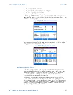
The digital fault reporter summary screen provides an indication that the fault report is
ready to capture data and has memory available. In protected mode, the
Ready to
Capture
indication is green when all of the following conditions hold.
•
The fault report feature is enabled.
•
The source for the fault report is properly configured.
•
The block trigger input is not asserted.
•
Memory is available.
•
A record capture is not currently in progress.
Otherwise the indication is red. In automatic overwrite mode, the
Ready to Capture
indication is green when all of the following conditions hold.


