


238
D90
PLUS
LINE DISTANCE PROTECTION SYSTEM – INSTRUCTION MANUAL
GROUPED PROTECTION ELEMENTS
CHAPTER 7: PROTECTION
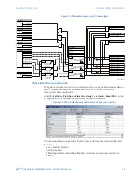
The
phase
directional overcurrent element is intended to apply a block signal to an
overcurrent element to prevent an operation when current is flowing in a particular
direction. The direction of current flow is determined by measuring the phase angle
between the current from the phase CTs and the line-line voltage from the VTs, based on
the 90° or quadrature connection. If there is a requirement to supervise overcurrent
elements for flows in opposite directions, such as can happen through a bus-tie breaker,
two phase directional elements should be programmed with opposite element
characteristic angle (ECA) settings.
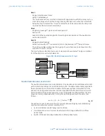
To increase security for three phase faults very close to the VTs used to measure the
polarizing voltage, a voltage memory feature is incorporated. This feature stores the
polarizing voltage the moment before the voltage collapses, and uses it to determine
direction. The voltage memory remains valid for one second after the voltage has
collapsed.
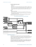
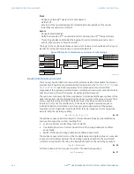
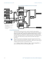
The main component of the phase directional element is the phase angle comparator with
two inputs: the operating signal (phase current) and the polarizing signal (the line voltage,
shifted in the leading direction by the characteristic angle, ECA).
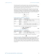
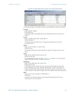
The following table shows the operating and polarizing signals used for phase directional
control.
Table 13: Phase directional overcurrent operating and polarizing signals
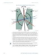
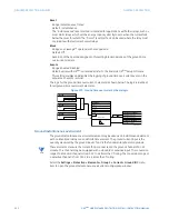
When the phase directional overcurrent element is disabled or the operating current is
below 5% × CT nominal, the element output is logic 0.
When the phase directional overcurrent element is enabled, the operating current is above
5% × CT nominal, and the polarizing voltage is above the
Voltage Cut Off Level
setting
value, the element output is dependent on the phase angle between the operating and
polarizing signals. The element output is logic 0 when the operating current is within
polarizing voltage ±90°; for all other angles, the element output is logic 1.
Once the voltage memory has expired, the phase overcurrent elements under directional
control can be set to block or trip on overcurrent. When the
Block When Voltage Memory
Expires
value is “Yes”, the directional element will block the operation of any phase
overcurrent element under directional control when voltage memory expires. When the
Block When Voltage Memory Expires
value is “No”, the directional element allows tripping of
phase overcurrent elements under directional control when voltage memory expires.
In all cases, directional blocking will be permitted to resume when the polarizing voltage
becomes greater than the polarizing voltage threshold.
NOTE
NOTE:
The phase directional element responds to the forward load current. In the case of a
following reverse fault, the element needs some time – in the order of 8 ms – to establish a
blocking signal. Some protection elements such as instantaneous overcurrent may
respond to reverse faults before the blocking signal is established. Therefore, a
coordination time of at least 10 ms must be added to all the instantaneous protection
elements under the supervision of the phase directional element. If current reversal is of a
concern, a longer delay – in the order of 20 ms – may be needed.
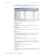
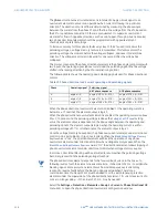
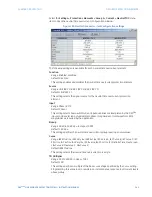
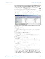
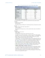
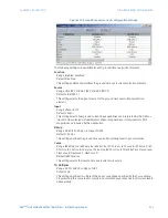
Select the
Settings > Protection > Elements > Group 1 > Current > Phase Directional OC
menu item to open the phase directional overcurrent configuration window.
Phase
Operating signal
Polarizing signal
ABC phase sequence
ACB phase sequence
A
angle of IA
angle of VBC × (1
∠
ECA)
angle of VCB × (1
∠
ECA)
B
angle of IB
angle of VCA × (1
∠
ECA)
angle of VAC × (1
∠
ECA)
C
angle of IC
angle of VAB × (1
∠
ECA)
angle of VBA × (1
∠
ECA)