CHAPTER 6: COMMUNICATIONS
COMMUNICATIONS OVERVIEW
D90
PLUS
LINE DISTANCE PROTECTION SYSTEM – INSTRUCTION MANUAL
89
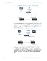
Figure 69: Simple single network topology with redundancy
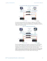
The topology below illustrates a dual LAN network. Configuration, and monitoring
functions are provided on LAN 1 with no redundancy. LAN 2 is dedicated to SCADA and
GOOSE communications and includes redundant hardware and media. Ports 2 and 3 are
configured for single IP redundancy.
Figure 70: Simple dual network topology
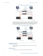
The topology below illustrates a dual redundant LAN network. Ports 2 and 3 are always
active. Each D90
Plus
device will serve clients on either network as required. GOOSE
messages are transmitted and received on both LANs simultaneously. Ports 2 and 3 are
configured for dual IP redundancy. In dual IP redundancy, both ports operate
independently. Loss of communication on one port does not result in connections being
closed or connections being transferred to the other port. With dual IP redundancy, both
GOOSE and GSSE messages are sent and received on both ports (there is no main or
alternate designation), but have a source MAC address of the sending port.
$&'5
3XEOLFQHWZRUN
*DWHZD\
/$16&$'$DQG*226(
0XOWL/LQN0/VZLWFK
85
VHULHV,('
3OXV
85
VHULHV,('
3OXV
(QHU9LVWD
VRIWZDUH
&38
&38
&RPPXQLFDWLRQV
&RPPXQLFDWLRQV
(QHU9LVWD9LHZSRLQW
0RQ0,
0XOWL/LQN0/
VZLWFK
$&'5
3XEOLFQHWZRUN
*DWHZD\
/$1
6&$'$DQG*226(
0XOWL/LQN0/VZLWFK
85
VHULHV,('
3OXV
85
VHULHV,('
3OXV
(QHU9LVWD
VRIWZDUH
&38
&38
&RPPXQLFDWLRQV
&RPPXQLFDWLRQV
6&$'$
0XOWL/LQN0/VZLWFK
0XOWL/LQN0/VZLWFK
/$1

