212
D90
PLUS
LINE DISTANCE PROTECTION SYSTEM – INSTRUCTION MANUAL
GROUPED PROTECTION ELEMENTS
CHAPTER 7: PROTECTION
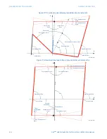
Quadrilateral Forward Outer
Range: 0.10 to 500.00 ohms in steps of 0.01
Default: 70.00 ohms
This setting specifies the forward reach of the outer quadrilateral characteristic. The
angle of this reach impedance is specified by the
Forward RCA
setting. The setting is not
used if the shape setting is “Mho”.
Forward RCA
Range: 40 to 90° in steps of 1
Default: 85°
This setting specifies the angle of the forward reach impedance for the mho
characteristics, angles of all the blinders, and both forward and reverse reach
impedances of the quadrilateral characteristics.
Reverse Reach
Range: 0.10 to 500.00 ohms in steps of 0.01
Default: 1.00 ohms
This setting specifies the reverse reach of all three mho characteristics and the inner
quadrilateral characteristic. For a simple system of a line and two equivalent sources,
this reach should be higher than the positive-sequence impedance of the local source.
Detailed transient stability studies may be needed for complex systems to determine
this setting. The angle of this reach impedance is specified by the
Reverse RCA
setting for
mho characteristics, and the
Forward RCA
setting for the inner quadrilateral
characteristic.
Quadrilateral Reverse Middle
Range: 0.10 to 500.00 ohms in steps of 0.01
Default: 60.00 ohms
This setting specifies the reverse reach of the middle quadrilateral characteristic. The
angle of this reach impedance is specified by the
Forward RCA
setting. The setting is not
used if the shape setting is “Mho”.
Quadrilateral Reverse Outer
Range: 0.10 to 500.00 ohms in steps of 0.01
Default: 70.00 ohms
This setting specifies the reverse reach of the outer quadrilateral characteristic. The
angle of this reach impedance is specified by the
Forward RCA
setting. The setting is not
used if the shape setting is “Mho”.
Reverse RCA
Range: 40 to 90° in steps of 1
Default: 85°
This setting specifies the angle of the reverse reach impedance for the mho
characteristics. This setting applies to mho shapes only.
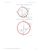
Outer Limit Angle
Range: 40 to 140° in steps of 1
Default: 120°
This setting specifies the outer power swing characteristic. The convention depicted in
the power swing detect characteristic should be observed: values greater than 90° result
in an apple-shaped characteristic; values less than 90° result in a lens shaped
characteristic. This angle must be selected in consideration of the maximum expected
load. If the maximum load angle is known, the outer limit angle should be coordinated
with a 20° security margin. Detailed studies may be needed for complex systems to
determine this setting. This setting applies to mho shapes only.


