CHAPTER 7: PROTECTION
CONTROL ELEMENTS
D90
PLUS
LINE DISTANCE PROTECTION SYSTEM – INSTRUCTION MANUAL
321
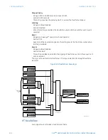
Group 2 Activate On, Group 3 Activate On, Group 4 Activate On, Group 5 Activate On,
Group 6 Activate On
Range: any FlexLogic™ operand or shared operand
Default: OFF
Each of these settings selects an operand which, when set, will activate the
corresponding setting group for use by any grouped element. A priority scheme ensures
that only one group is active at a given time. The highest-numbered group activated by
these settings takes priority over the lower-numbered groups. There is no activation
setting group 1 (the default active group) since group 1 automatically becomes active
when there is no other group active.
Group 1 Name, Group 2 Name, Group 3 Name, Group 4 Name, Group 5 Name, Group 6
Name
Range: up to 16 alphanumeric characters
Default: empty
These settings allows to user to assign a name to each of the six settings groups.
Events
Range: Enabled, Disabled
Default: Disabled
This setting enables and disables the logging of setting group control events in the
sequence of events recorder.
The
Current Setting Group
actual value is also displayed in this menu.
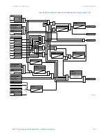
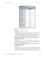
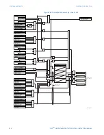
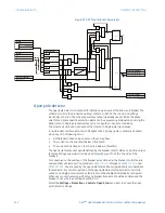
FlexLogic™ control of a settings group
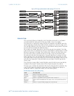
The relay can be set up via a protection FlexLogic™ equation to receive requests to
activate or de-activate a particular non-default settings group. The following FlexLogic™
equation illustrates requests via remote communications (for example,
VIRT IP 1 ON
) or from
a local contact input (for example,
CONT IP 1 ON
) to initiate the use of a particular settings
group, and requests from several overcurrent pickup measuring elements to inhibit the use
of the particular settings group. The assigned
VIRT OP 1
operand is used to control the “On”
state of a particular settings group.
Figure 262: FlexLogic™ control of a settings group
9,57,3219,
&217,321+$
25
25
3+$6(72&3.3
127
3+$6(72&3.3
127
$1'
$1'
9,572392
9,572392
(1'
$&'5

