178
D90
PLUS
LINE DISTANCE PROTECTION SYSTEM – INSTRUCTION MANUAL
POWER SYSTEM
CHAPTER 7: PROTECTION
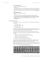
It is possible to select the sum of two CTs for a protection source. The first channel
displayed is the CT to which all others will be referred. For example, the selection “J1+J4”
indicates the sum of each phase from channels J1 and J4, scaled to whichever CT has the
higher ratio.
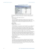
The approach used to configure the protection sources is detailed below.
1.
Specify the ratio and nominal secondary current for each CT input.
2.
Specify the connection type, ratio, and nominal secondary voltage for each VT input.
3.
Specify the configuration for each source, including the CTs to be summed together.
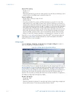
The following settings are available for each protection source.
Name
Range: up to 20 alphanumeric characters
Default: LINE
This setting specifies a name for the protection source.
Phase CT
Range: None, J1, J4, J1+J4, etc.
Default: J1+J4
This setting selects a phase CT or sum of phase CTs to represent the protection source.
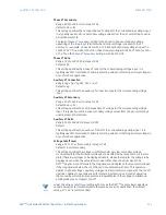
Ground CT
Range: None, J7
Default: J7
This setting selects a ground CT to represent the protection source.
Phase VT
Range: None, J10
Default: J10
This setting selects a phase VT to represent the protection source.
Auxiliary VT
Range: None, J8, J9
Default: None
This setting selects an auxiliary VT to represent the protection source.
Internal disturbance detection
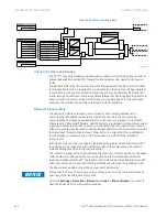
The disturbance detection element (ANSI 50DD) is a sensitive current disturbance detector
that detects any disturbance on the protected system. This element is intended for use in
conjunction with measuring elements, blocking of current based elements (to prevent
maloperation as a result of the wrong settings), and starting oscillography data capture. A
disturbance detector is provided for each source.
The disturbance detector responds to the changes in magnitude of the sequence currents.
The disturbance detector also responds to the change in currents of twice the current cut-
off level. The default cut-off threshold is 0.02 pu. As such, the disturbance detector
responds to a change of 0.04 pu by default. The
Current Cutoff
setting (located in the
Settings > Protection > Power System > AC Input - Current
menu) controls the metering
sensitivity of the disturbance detector.
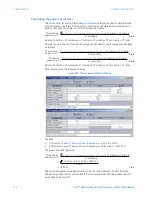
The source 1 disturbance detector logic is shown below. The logic is identical for all three
sources.

