background image

CHAPTER 12: LOCAL INTERFACE

MIMIC DIAGRAM EDITOR

D90

PLUS

 LINE DISTANCE PROTECTION SYSTEM – INSTRUCTION MANUAL

595

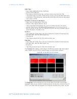
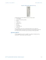
Figure 521: Pre-configured mimic diagram 1 (breaker-and-a-half scheme)

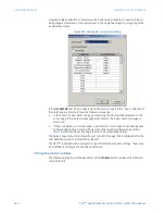
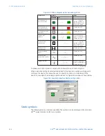
Figure 522: Pre-configured mimic diagram 2 (breaker-and-a-half scheme with breaker 

disconnects)

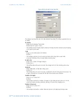
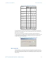
Figure 523: Pre-configured mimic diagram 3 (breaker-and-a-half scheme, with breaker 

and line disconnects)

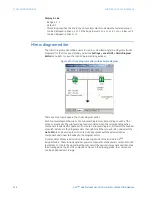
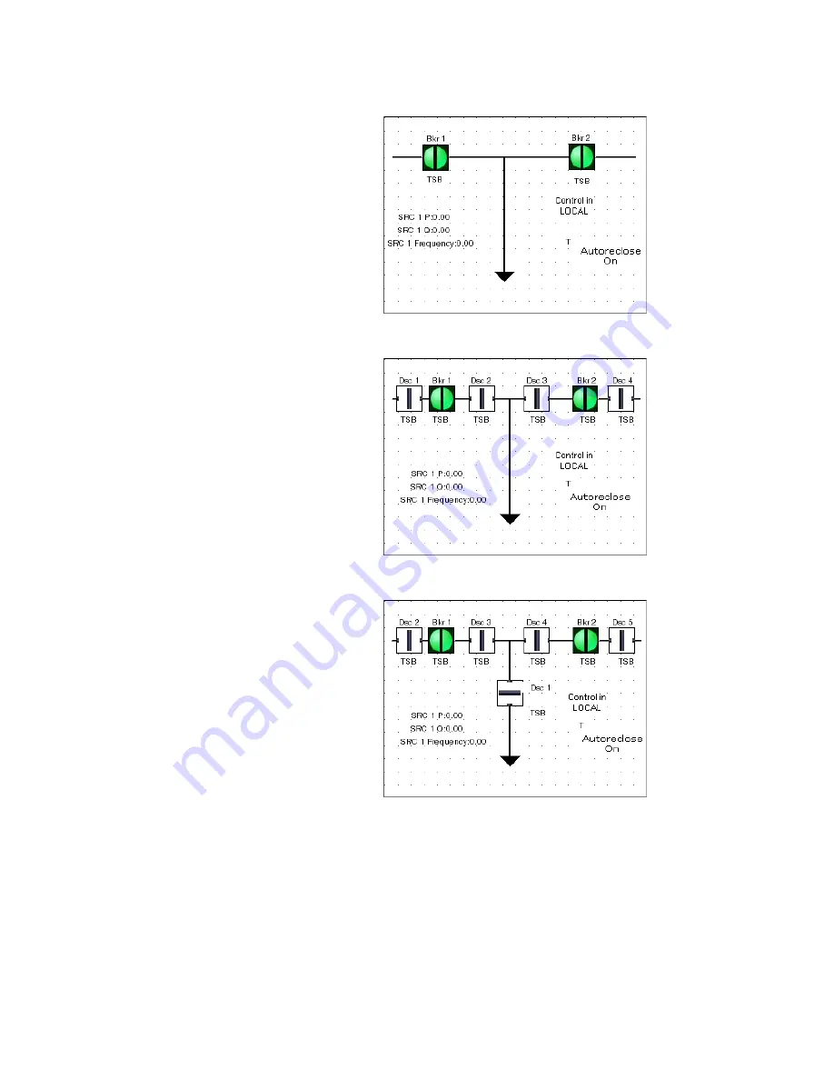
Figure 524: Pre-configured mimic diagram 4 (breaker-and-a-half scheme, with breaker, 

Summary of Contents for D90 Plus

Page 1: ...E Grid Solutions Instruction Manual Product version 1 8x GE publication code 1601 9019 E5 GEK 113248E D90Plus Line Distance Protection System 1601 9019 E5 IISO 9001 G N E I L M I U T L TE S I R G E E D R ...

Page 2: ... Multilin and GE Multilin are trademarks or registered trademarks of GE Multilin Inc The contents of this manual are the property of GE Multilin Inc This documentation is furnished on license and may not be reproduced in whole or in part without the permission of GE Multilin The content of this manual is for informational use only and is subject to change without notice Part number 1601 9019 E5 Oc...

Page 3: ...SCRIPTION Device overview 15 Front panel interface 16 Protection features 17 Automation features 21 Equipment manager features 22 Metering and monitoring features 22 Digital fault recorder features 23 Communications features 25 Order codes 25 Specifications 25 Protection specifications 26 Automation specifications 37 Equipment manager 38 Metering specifications 39 Digital fault recorder specificat...

Page 4: ...s Setup 77 Extended EnerVista URPlus Setup features 77 Setting templates 77 Securing and locking FlexLogic equations 82 Settings file traceability 83 6 COMMUNICATIONS Communications overview 87 Ethernet network topology 87 Network settings 90 Ethernet ports 90 TFTP protocol 94 SNTP protocol 95 HTTP protocol 96 Network filtering 97 Ethernet actual values 98 Remaining TCP IP connections actual value...

Page 5: ...guration 157 Teleprotection channel tests 158 Teleprotection commands 158 Inter relay communications 159 Inter relay communication actual values 160 Inter relay communication commands 162 Communication logic operands 163 Customizing the communication logic operands 164 Communication FlexAnalog parameters 164 7 PROTECTION Protection overview 167 Introduction to protection elements 167 Power system ...

Page 6: ...nds 413 Protection FlexLogic operands 414 Protection FlexAnalog parameters 426 8 AUTOMATION Automation controller overview 429 Input and output structure 430 Breakers 431 Breaker control 431 Breaker interlocking 434 Disconnects 436 Disconnect configuration 436 Disconnect control 441 Disconnect interlocking 444 Automation control 446 Front panel status and control 446 Local remote control scheme 44...

Page 7: ...er settings 515 Disturbance recorder 520 Front panel indications 522 Disturbance recorder settings 523 Using shared operands in the digital fault recorder 528 Shared digital fault recorder operands 529 Digital fault recorder FlexAnalog parameters 530 11 METERING Metering source 533 Phasor measurement unit 533 Phasor measurement unit configuration 534 Phasor measurement unit calibration 535 Phasor ...

Page 8: ...3 SECURITY Password security 609 Password security settings 610 Password security operation 612 EnerVista security management system 613 Enabling the security management system 613 Adding a new user 613 Modifying user privileges 614 14 TESTING Test mode 617 Force contact inputs 617 Force contact outputs 618 Self tests 619 Self test error messages 620 Self test logic operands 625 15 THEORY OF OPERA...

Page 9: ...ase selection 656 Communications channels for pilot aided schemes 657 Permissive echo signaling 664 Pilot scheme and phase selector coordination 665 Cross country fault example 666 16 MAINTENANCE General maintenance 669 Back up and restore settings 669 Back up settings 669 Restore settings 670 Upgrade software 670 Upgrade firmware 671 Uninstall and clear files and data 672 Repairs 672 Storage 672 ...

Page 10: ...x D90PLUS LINE DISTANCE PROTECTION SYSTEM INSTRUCTION MANUAL TABLE OF CONTENTS ...

Page 11: ...and equipment symbols are used in this document DANGER DANGER Indicates a hazardous situation which if not avoided will result in death or serious injury WARNING IMPORTANT Indicates a hazardous situation which if not avoided could result in death or serious injury CAUTION CAUTION Indicates a hazardous situation which if not avoided could result in minor or moderate injury NOTICE FASTPATH Indicates...

Page 12: ... and auxiliaries significantly These devices also transfer data to central control facilities and human machine interfaces using electronic communications The functions performed by these products have become so broad that many users now prefer the term IED Intelligent Electronic Device It is obvious to station designers that the amount of cabling and auxiliary equipment installed in stations can ...

Page 13: ...unctions provided by the device The CPU receives analog and digital data from the AC and input output modules The data is processed by the CPU and resulting control actions are sent back to the input output modules The CPU has one rear Ethernet port that is used for configuration and record retrieval and one rear RS485 port supporting the Modbus and DNP protocols The CPU also contains the IRIG B p...

Page 14: ...nctions Protection Automation Metering 5 3URWHFWLRQ XWRPDWLRQ TXLSPHQW PDQDJHU LJLWDO IDXOW UHFRUGHU 0HWHULQJ RFDO 0 RQWDFW RXWSXWV 9LUWXDO RXWSXWV 226 66 RQWDFW LQSXWV 9LUWXDO LQSXWV 7 LQSXWV 97 LQSXWV 226 66 0 6 QHU9LVWD VRIWZDUH QDORJ PHDVXUHPHQW RI FRQWDFW VWDWH RPPXQLFDWLRQV PRGXOH DVH 7 DVH 6LQJOH JURXQGLQJ VWXG IRU VLPSOLILHG ZLULQJ 5XJJHG FKDVVLV WR 7ZR WLHUHG GDJJHUHG WHUPLQDO EORFNV HDV ...

Page 15: ...rical recording of selected metering quantities and includes statistical maximum minimum and average and alarming capabilities The metering function also provides synchrophasor capabilities in accordance with IEEE C37 118 2005 The digital fault recorder incorporates transient recorder disturbance recorder and fault report capabilities The transient recorder is intended to capture short events such...

Page 16: ...SHUDQGV 9LUWXDO LQSXWV 6KDUHG RSHUDQGV XWRPDWLRQ 9LUWXDO DQDORJ YDOXHV OH QDORJ YDOXHV OHPHQWV XWRPDWLRQ ORJLF XWRPDWLRQ RSHUDQGV 9LUWXDO LQSXWV 6KDUHG RSHUDQGV LJLWDO IDXOW UHFRUGHU OH QDORJ YDOXHV TXLSPHQW PDQDJHU 6KDUHG RSHUDQGV 0HWHULQJ URQW SDQHO 0 5HPRWH LQSXWV XWRPDWLRQ FRQWDFW LQSXWV 3URWHFWLRQ FRQWDFW LQSXWV 7V DQG 97V 63 XWRPDWLRQ FRQWDFW RXWSXWV 5 OH QDORJV 9LUWXDO RXWSXWV 3URWHFWLRQ RS...

Page 17: ...For additional information refer to Main processor module on page 51 EnerVista software The EnerVista software suite is an industry leading set of programs that simplifies every aspect of the D90Plus The EnerVista suite provides tools to monitor the status of your protected asset maintain the device and integrate information measured by the D90Plus into DCS or SCADA monitoring systems Convenient C...

Page 18: ... or higher in high color mode 16 bit color USB 2 0 or Ethernet port for communications to the IED Installing the software After ensuring the minimum requirements for using EnerVista URPlus Setup software see previous section use the following procedure to install the EnerVista URPlus Setup from the enclosed GE EnerVista CD 1 Insert the GE EnerVista CD into your CD ROM drive 2 Click the Install Now...

Page 19: ...uding the new directory name where the EnerVista URPlus Setup will be installed 7 Click on Next to begin the installation The files will be installed in the directory indicated and the installation program will automatically create icons and add EnerVista URPlus Setup to the Windows start menu 8 Click Finish to end the installation The URPlus series device will be added to the list of installed IE...

Page 20: ...the device The faceplate USB port is intended for local use and is not described in this section refer to the Using the Quick Connect Feature section for details on configuring the USB port 1 Verify that the latest version of the EnerVista URPlus Setup software is installed available from the GE EnerVista CD or online from http gegridsolutions com multilin See the Software Installation section for...

Page 21: ... upload the order code due to a communications error ensure that the EnerVista URPlus Setup serial communications values entered in the previous step correspond to the relay setting values 11 Click OK when the relay order code has been received The new device will be added to the Site List window or Online window located in the top left corner of the main EnerVista URPlus Setup window The site dev...

Page 22: ...red name in the Device Name field and a description optional of the site 9 Select Ethernet from the Interface drop down list This will display a number of interface parameters that must be entered for proper Ethernet functionality 10 Enter the device IP address specified in the Settings Communications Network Addressing menu in the IP Address field 11 Enter the relay slave address and Modbus port ...

Page 23: ...s device from the EnerVista Launchpad to start EnerVista URPlus Setup 3 Click the Quick Connect button to open the Quick Connect dialog box 4 Select the Interface and the correct USB device then click Connect 5 The EnerVista URPlus Setup software will create a site named Quick Connect with a corresponding device also named Quick Connect and display them on the upper left corner of the screen Expan...

Page 24: ...en properly setup for communications If a relay icon appears in place of the status indicator than a report such as an oscillography or event record is open Close the report to re display the green status indicator 3 The breaker settings can now be edited printed or changed according to user specifications Refer to chapter 4 in this manual and the EnerVista URPlus Setup help file for more informat...

Page 25: ...an trip in less than one power system cycle for source impedance ratios SIR up to 30 The key benefits of the D90Plus are listed below Secure subcycle protection ensures trip times less than one cycle Reliable and secure protection on lines equipped with series compensation Superior phase selection algorithm ensures secure high speed single pole tripping Simplified programmable automation controlle...

Page 26: ...90Plus provides an embedded configurable color LCD annunciator on the front panel of the device eliminating the need for LEDs and separate annunciators in the panel Any contact direct or remote input or internally generated operand can be assigned to the annunciator Up to 288 targets may be assigned The display can be configured for 12 24 or 48 alarms per page to a maximum of 24 pages A separate s...

Page 27: ...ional or reverse This allows customization to a variety of applications including primary line protection backup protection for busbars and backup protection for generators transformers and reactors The D90Plus can be applied to power systems with different earthing conditions lines with in zone transformers or tapped transformer feeders and overhead lines with series compensation Each zone elemen...

Page 28: ...rs allowing application of the D90Plus for backup protection on generators VTs and CTs can be installed independently of each other on either side of the power transformer The relay automatically compensates for transformer connections to guarantee accurate reach for any type of fault For additional information refer to Phase distance settings on page 186 Phase distance applied to power transforme...

Page 29: ...wer swings characterized by fluctuating currents and voltages This can result in unwanted tripping since distance elements can respond to these power swings as faults The D90Plus built in power swing detection element provides both power swing blocking and out of step tripping functions The element measures the positive sequence apparent impedance and traces its locus with respect to either a two ...

Page 30: ...lements Time overcurrent elements can individually be set to use IEEE IEC or custom FlexCurves For additional information refer to Current elements on page 226 Autoreclose The D90Plus provides multi shot autoreclosing for single pole or three pole autoreclose on all types of faults with independently programmable dead times for each shot Autoreclosing also can be dynamically blocked by user progra...

Page 31: ...ction automatically notifies the users of errors such as overflows type mismatch division by zero and square root of a negative number allowing the user to achieve maximum optimization The programming interface complies with the global standard IEC 61131 for industrial control programming and also allows for embedded comments Easy to use on line and off line debugging and simulation tools provide ...

Page 32: ...essure stages and the circuit breaker trip and close coil monitoring to alert the operator an impending circuit breaker problem Up to two breakers associated trip close coils and station battery can be monitored in real time These features are available through the front panel interface in real time allowing the operating personnel to detect any abnormality and take corrective actions A comprehens...

Page 33: ...values and phasor representations for phase current ground current phase voltage and auxiliary voltage are displayed via the front panel interface or through the EnerVista URPlus Setup software Sequence components metering The metered values and phasor representations for negative sequence current and voltage positive sequence current and voltage and zero sequence current and voltage are displayed...

Page 34: ...port and associated fault location data The fault report stores data pertinent to an event that is triggered and provides the distance to the fault location A maximum of 15 records are stored in the nonvolatile memory providing a comprehensive summary of events associated with a fault Transient recorder The transient recorder captures critical system data during a transient event It is tailored to...

Page 35: ...ole sub cycle distance protection series Automation S E Communications 01 Modbus TCP IP DNP 3 0 serial and serial Modbus 02 Modbus TCP IP and IEC 61850 03 Modbus TCP IP IEC 61850 and DNP 3 0 TCP IP 04 Modbus TCP IP IEC 61850 and IEC 60870 5 104 Metering S P L U Digital fault recorder S Transient recorder and sequence of events recorder D Transient recorder sequence of even ts recorder and disturba...

Page 36: ...0 5 of reading from 10 to 208 V Curve shapes GE IAV inverse definite time Curve multiplier 0 00 to 600 00 in steps of 0 01 Timing accuracy 3 of operate time or 4 ms whichever is greater BREAKER FAILURE Mode single pole three pole Current supervision phase current neutral current Supervision pickup 0 001 to 30 000 pu in steps of 0 001 Supervision dropout 98 of pickup Supervision accuracy at 0 1 to ...

Page 37: ...TOR 50DD Type sensitive current disturbance detector Range 0 004 to 0 04 pu twice the current cut off level threshold FLEXCURVES Number 4 A through D Reset points 40 0 through 1 of pickup Operate points 80 1 through 20 of pickup Time delay 0 to 65535 ms in steps of 1 FLEXELEMENTS Elements 16 Operating signal any analog actual value or two values in differential mode Operating signal mode signed or...

Page 38: ...ator limit angle 30 to 90 in steps of 1 Characteristic angle 30 to 90 in steps of 1 Limit angle 30 to 90 in steps of 1 Z0 Z1 magnitude 0 00 to 10 00 in steps of 0 01 Z0M Z1 angle 90 to 90 in steps of 1 Z0M Z1 magnitude 0 00 to 7 00 in steps of 0 01 Z0 Z1 angle 90 to 90 in steps of 1 Right and left blinder reach 0 02 to 500 00 ohms in steps of 0 01 Right and left blinder characteristic angle 60 to ...

Page 39: ... 6 5 6 5 6 5 6 5 6 5 6 5 VRXUFH LPSHGDQFH UDWLR DXOW ORFDWLRQ RI UHOD VHWWLQJ 6WDQGDUG JURXQG GLVWDQFH 2SHUDWLQJ WLPH F FOHV DXOW ORFDWLRQ RI UHOD VHWWLQJ 6XE F FOH JURXQG GLVWDQFH ZLWKRXW 97 ILOWHU 2SHUDWLQJ WLPH F FOHV 6 5 6 5 6 5 6 5 6 5 DXOW ORFDWLRQ RI UHOD VHWWLQJ 6XE F FOH JURXQG GLVWDQFH ZLWK 97 ILOWHU 2SHUDWLQJ WLPH F FOHV 6 5 6 5 6 5 6 5 6 5 ...

Page 40: ...Moderately Inverse IEEE Very Inverse IEEE Extremely Inverse IEC BS A IEC BS B IEC BS C IEC Short Inverse IAC Inverse IAC Short Inverse IAC Very Inverse IAC Extremely Inverse I2t FlexCurves programmable definite time 0 01 second base curve Curve multiplier 0 01 to 600 00 in steps of 0 01 Reset type instantaneous timed per IEEE Timing accuracy for 1 03 to 20 pickup 3 5 of operating time or 1 cycle w...

Page 41: ...elay 0 00 to 600 00 seconds in steps of 0 01 Operate time 20 ms at 3 pickup at 60 Hz Timing accuracy for operation at 1 5 pickup 3 or 4 ms whichever is greater NEGATIVE SEQUENCE OVERVOLTAGE Pickup level 0 000 to 1 250 pu in steps of 0 001 Dropout level 98 of pickup Level accuracy 0 5 of reading from 10 to 208 V Pickup delay 0 00 to 600 00 seconds in steps of 0 01 Reset delay 0 00 to 600 00 seconds...

Page 42: ... operation at 1 5 pickup 3 or 4 ms whichever is greater NEUTRAL OVERVOLTAGE Pickup level 0 000 to 1 250 pu in steps of 0 001 Dropout level 98 of pickup Level accuracy 0 5 of reading from 10 to 208 V Pickup delay 0 00 to 600 00 seconds in steps of 0 01 definite time or user defined curve Reset delay 0 00 to 600 00 seconds in steps of 0 01 Timing accuracy 3 or 20 ms whichever is greater Operate time...

Page 43: ...2 Tripping operation time 12 ms typically reverse load forward fault Blocking operation time 8 ms typically forward load reverse fault PHASE DISTANCE Characteristic mho memory polarized or offset or quad memory polarized or non directional selectable individually per zone Zones 5 Directionality forward reverse or non directional per zone Reach 0 02 to 250 00 ohms in steps of 0 01 secondary ohms Re...

Page 44: ...5 DXOW ORFDWLRQ RI UHOD VHWWLQJ 6 5 6 5 6 5 6 5 6 5 2SHUDWLQJ WLPH F FOHV 6 5 VRXUFH LPSHGDQFH UDWLR 6WDQGDUG SKDVH GLVWDQFH DXOW ORFDWLRQ RI UHOD VHWWLQJ 2SHUDWLQJ WLPH F FOHV 6 5 6 5 6 5 6 5 6 5 6XE F FOH SKDVH GLVWDQFH ZLWK 97 ILOWHU 2SHUDWLQJ WLPH F FOHV DXOW ORFDWLRQ RI UHOD VHWWLQJ 6 5 6 5 6 5 6 5 6 5 6XE F FOH SKDVH GLVWDQFH ZLWKRXW 97 ILOWHU ...

Page 45: ...kup level 0 000 to 30 000 pu in steps of 0 001 Dropout level 98 of pickup Level accuracy at 0 1 to 2 0 CT 0 5 of reading or 1 of rated whichever is greater Level accuracy at 2 0 CT 1 5 of reading Curve shapes IEEE Moderately Inverse IEEE Very Inverse IEEE Extremely Inverse IEC BS A IEC BS B IEC BS C IEC Short Inverse IAC Inverse IAC Short Inverse IAC Very Inverse IAC Extremely Inverse I2t FlexCurv...

Page 46: ...ion keypad programmable Lines of code 512 Internal variables 64 Supported operations NOT XOR OR 2 to 16 inputs AND 2 to 16 inputs NOR 2 to 16 inputs NAND 2 to 16 inputs latch reset dominant edge detectors timers Inputs any logical variable contact or virtual input Number of timers 32 Pickup delay 0 to 60000 ms seconds or minutes in steps of 1 Dropout delay 0 to 60000 ms seconds or minutes in steps...

Page 47: ...01 Time accuracy 3 or 20 ms whichever is greater Operate time 30 ms at 60 Hz Automation specifications AUTOMATION LOGIC Number of lines of logic 4096 Number of blocks 1 Edit and view capability yes Logic type cyclic Programming language proprietary Execution rate 50 ms Variable types Boolean IEEE floating point Boolean operations NOT XOR OR AND NOR NAND any contact input any direct input any telep...

Page 48: ...trol inputs step up and three bit Power up mode restore from non volatile memory or synchronize to a three bit control input or synchronize restore mode SYNCHROCHECK Elements 2 Maximum voltage difference 0 to 100000 volts in steps of 1 Maximum angle difference 0 to 100 in steps of 1 Maximum frequency difference 0 00 to 2 00 Hz in steps of 0 01 Hysteresis for maximum frequency difference 0 00 to 0 ...

Page 49: ...rrent signal is used for frequency measurement Accuracy at I 0 25 pu 0 001 Hz when current signal is used for frequency measurement PHASOR MEASUREMENT UNIT Output format per IEEE C37 118 standard Channels 14 synchrophasors 8 analogs 16 digitals TVE total vector error 1 Triggering frequency voltage current power rate of change of frequency user defined Reporting rate 1 2 5 10 12 15 20 25 30 50 or 6...

Page 50: ...block Storage modes automatic overwrite protected Triggering modes time window from rising edge of trigger continuous recording as long as trigger is active Pre trigger window 0 to 100 Data storage non volatile memory EVENT RECORDER Storage capacity 8192 events Time tag to 1 ms Triggers any contact input direct input remote input virtual input logic operand or self test event Data storage non vola...

Page 51: ... time window from rising edge of trigger continuous recording as long as trigger is active Pre trigger window 0 to 100 Data storage non volatile memory Front panel interface ANNUNCIATOR Inputs 288 Windows per page 12 to 48 Pages up to 24 Sequence manual reset locking Off indication alarm inactive and reset Flashing indication alarm active and not acknowledged alarm inactive and not acknowledged On...

Page 52: ...Relay burden 0 2 VA secondary Conversion range 0 02 to 46 CT rating RMS symmetrical Current withstand 20 ms at 250 rated 1 second at 100 rated continuous at 3 rated AC VOLTAGE VT rated secondary 50 0 to 240 0 V VT ratio 1 00 to 24000 0 Nominal frequency 50 or 60 Hz Relay burden 0 25 VA at 120 V Conversion range 1 to 275 V Voltage withstand continuous at 260 V to neutral 1 minute per hour at 420 V ...

Page 53: ...ations module 100Base FX media type 1300 nm multi mode half full duplex fiber optic with ST connector 10 100Base TX media type RJ45 connector Power budget 10 dB Maximum optical input power 14 dBm Receiver sensitivity 30 dBm Typical distance 2 0 km SNTP clock synchronization 10 ms typical FORM A RELAY Make and carry for 0 2 s 30 A per ANSI C37 90 Carry continuous 6 A Break at L R of 40 ms 0 250 A D...

Page 54: ...tion yes no Data rate 64 or 128 kbps CRC 32 bit CRC alarm responding to rate of messages failing the CRC CRC alarm monitoring message count 10 to 10000 in steps of 1 CRC alarm threshold 1 to 1000 in steps of 1 Unreturned messages alarm responding to rate of unreturned messages in the ring Unreturned messages alarm monitoring message count 10 to 10000 in steps of 1 Unreturned messages alarm thresho...

Page 55: ...al losses vary from one installation to another the distance covered by your system may vary LINK LOSSES 850 NM LASER MULTIMODE MODULE ST connector losses 2 dB total of both ends 50 125 μm fiber loss 2 5 dB km 62 5 125 μm fiber loss 3 0 dB km Splice loss one splice every 2 km at 0 05 dB loss per splice System margin 3 dB of additional loss was added to calculations to compensate for all other loss...

Page 56: ... 60255 25 CISPR 11 22 class A Insulation resistance IEC 60255 5 Dielectric strength IEC 60255 5 ANSI IEEE C37 90 Dielectric across relay contacts IEEE C37 90 1 6 kV Electrostatic discharge EN 61000 4 2 IEC60255 22 2 8 kV C 15 kV A L4 Voltage dips interruptions variations IEC 61000 4 11 30 1 cycle IEC 60255 11 AC ripple IEC 61000 4 17 standard Interruptions on DC power IEC61000 4 29 Damped magnetic...

Page 57: ...nsions The case dimensions are shown below along with cutout details for panel mounting When planning the location of your panel cutout ensure that provision is made for the faceplate to swing open without interference to or from adjacent equipment The D90Plus must be mounted such that the faceplate sits semi flush with the panel or switchgear door allowing the operator access to the front panel k...

Page 58: ... the D90Plus are represented by three characters assigned in order by module slot position row number and column letter See the following figure for an example of rear terminal assignments 870725A2 CDR 7 13 181 1 mm CUTOUT 17 75 450 8 mm 18 37 466 6 mm 1 57 39 8 mm 4 00 101 6 mm 4 0 28 diameter 7 1 mm 9 80 249 mm 11 43 290 mm 7 50 190 mm 18 31 465 mm 18 86 479 mm 870706A2 CDR 7 00 178 mm Mounting ...

Page 59: ...AL 49 Figure 19 Rear terminal view Electrical installation This section describes the electrical installation of the D90Plus Typical wiring A typical wiring diagram for the D90Plus is shown below This diagram provides an example of how to wire the device Actual wiring will vary according to application 5 ...

Page 60: ...d automation controller 10 100Base TX 100Base FX 100Base FX 10 100Base TX Ethernet Ethernet COMMS BNC 100Base FX 10 100Base TX Ethernet IRIG B input RS485 CPU D_3a D_1a D_2a Common Computer running EnerVista software J E K D F H G A Inputs outputs Inputs outputs Inputs outputs Inputs outputs Inputs outputs CPU Comms Inter relay comms Power supply AC inputs Shaded modules are optional Critical fail...

Page 61: ...r and numerical aperture of each fiber must be the same In order to engage or disengage the ST type connector only a quarter turn of the coupling is required DANGER DANGER Observing any fiber transmitter output may cause injury to the eye CAUTION CAUTION Ensure the dust covers are installed when the fiber is not in use Dirty or scratched connectors can lead to high losses on a fiber link RS485 por...

Page 62: ...device should also be daisy chained to the next one in the link A maximum of 32 devices can be connected in this manner without exceeding driver capability For larger systems additional serial channels must be added It is also possible to use commercially available repeaters to increase the number of devices on a single channel to more than 32 Star or stub connections should be avoided entirely Li...

Page 63: ...s at 100 Mbps Optical fiber may be connected to the D90Plus supporting a wavelength of 1310 nm in multi mode The optical fiber sizes supported are 50 125 µm and 62 5 125 µm The fiber optic port is designed such that the response times will not vary for any core that is 62 5 µm or less in diameter For optical power budgeting splices are required every 1 km for the transmitter receiver pair When spl...

Page 64: ...uced by a VT or CVT Likewise channel 11 is intended for connection to phase B and channel 12 is intended for connection to phase C The phase voltage channels are used for most metering and protection purposes Channels 8 and 9 are intended for connection to single phase sources In the D90Plus each of these inputs are typically used to measure the voltage on the side of the breaker opposite to the l...

Page 65: ... The CT secondaries should be connected to the AC terminals of the D90Plus through a shorting type test switch or shorting type terminal blocks in order to facilitate safe withdrawal of the AC module There are no internal ground connections on the current inputs Current transformers with 1 to 50000 A primaries and 1 A or 5 A secondaries may be used CT connections for both ABC and ACB phase rotatio...

Page 66: ...used for the outputs of one relay There are options of using current or voltage detection for feature supervision depending on the module ordered All inputs and outputs are isolated from one another with each input and output having two dedicated terminals Since an entire module row is used for a single contact input or output the name is assigned using the module slot position and row number D 1 ...

Page 67: ... is energized If the relay contacts need to be used for low voltage accessible applications it is the customer s responsibility to ensure proper insulation levels NOTE NOTE When current monitoring is used to seal in the form A and solid state relay contact outputs the FlexLogic operand driving the contact output should be given a reset delay of 10 ms to prevent damage of the output contact in situ...

Page 68: ...ntact does not attempt to break the energized inductive coil circuit and weld the output contacts NOTE NOTE There is no provision in the relay to detect a DC ground fault on 48 V DC control power external output We recommend using an external DC supply Contact input output module configuration There are six types of contact input and output modules available for the D90Plus Type A eight contact in...

Page 69: ... 2 Form A output 2 Form A output 2 Contact input 4 Form A output 2 3A Form A output 3 SSR output 3 Form A output 3 Form A output 3 Contact input 5 Form A output 3 3B Form A output 3 SSR output 3 Form A output 3 Form A output 3 Contact input 6 Form A output 3 4A Form A output 4 SSR output 4 Form A output 4 Form A output 4 Contact input 7 Form A output 4 4B Form A output 4 SSR output 4 Form A output...

Page 70: ...Rx2 and URPlus2 Tx2 to URPlus1 Rx2 for the second ring 6B Contact input 2 Contact input 2 Contact input 2 Form A output 6 Contact input 12 Form A output 6 7A Contact input 3 Contact input 3 Contact input 3 Form A output 7 Contact input 13 Form A output 7 7B Contact input 3 Contact input 3 Contact input 3 Form A output 7 Contact input 14 Form A output 7 8A Contact input 4 Contact input 4 Contact in...

Page 71: ...connectors Table 3 Channel communication options DANGER DANGER The 850 nm module uses a class 1 VCSEL laser which is very harmful to the eye Observing any fiber transmitter output may cause serious injury to the eye Direct input and output link LEDs The link LEDs for channels 1 and 2 are located on the rear of the inter relay communications card as shown below Module Specification B G 703 64 128 k...

Page 72: ...a Signal detected and receiving valid data yellow bit alarm not set Signal detected receiving valid data and the received yellow bit alarm is set the yellow bit indicates that remote unit is not receiving valid data Direct fiber Loss of signal Signal detected but not receiving valid data Signal detected and receiving valid data Not used G 703 Loss of signal Signal detected but not receiving valid ...

Page 73: ...mmon to see pinouts numbered TxA TxB RxA and RxB In such cases it can be assumed that A is equivalent to and B is equivalent to RS422 communication interface The RS422 inter relay communications module is a dual channel dual clock RS422 interface The module can be configured to run at 64 or 128 kbps AWG 24 twisted shielded pair cable is recommended for external connections The module is protected ...

Page 74: ...ansmit timing clock of the multiplexer interface is sampling the data in the center of the transmit data window Therefore it is important to confirm clock and data transitions to ensure proper system operation For example the following figure shows the positive edge of the Tx clock in the center of the Tx data bit 5 7 6KLHOG 20 7 ORFN 5 ORFN 5 56 FRPPXQLFDWLRQV E E E E D D D D 56 FKDQQHO 7 7 ORFN ...

Page 75: ...l link for synchronous data between a multiplexer and a teleprotection device This data is typically 64 kbps but the standard provides for speeds up to 64n kbps where n 1 2 12 The URPlus series C37 94 communication modules are either 64 kbps with n fixed at 1 for 128 kbps with n fixed at 2 The frame is a valid International Telecommunications Union ITU T recommended G 704 pattern from the standpoi...

Page 76: ...94 protocol selection If the setting is programmed as C37 94 Internal Clock then the system clock is generated internally For an external or loop timing scheme the system clock is derived from the received line signal For these cases the program the setting to C37 94 External Clock or Default for connection to higher order systems The URPlus series direct fiber module can be connected directly to ...

Page 77: ...pushbuttons located at the bottom of the display are for navigation while the pushbuttons located at both sides of the display are dedicated for control functions The annunciator is a color LCD display that provides alarm and trip information The annunciator also provides indication of any active self diagnostic messages and includes a product information screen Figure 40 Front panel interface 5XJ...

Page 78: ...ns for control functions This display provides convenient access to operational data generated by the D90Plus It also enables local control of power system devices that are connected to the IED The control pushbuttons are shown only in the control menu Otherwise the menu navigation pushbuttons will be shown The number of control pushbuttons is dependent on the number of disconnects and breakers in...

Page 79: ...graphically displays the phasor components of the system voltage phase neutral and current for the selected metering source The sequence screen graphically displays the sequence components of the system voltage and currents for the selected metering source Control menu The control menu provides the option to select a control diagram view or select one of the user programmable pushbutton views The ...

Page 80: ...kers disconnect switches local remote status or autoreclose The selected component display is shown below Figure 45 Mimic page Selected breaker with operate actions menu and dynamic display of current phase angle The front panel control pushbuttons can be placed under password security When password security is enabled the front panel will request the command password before performing any actions...

Page 81: ...gured for protected mode then the enabled indicator will also switch to red indicating that new records will be captured If the function is configured for automatic overwrite then the element will overwrite old records and the enabled LED will remain green For additional details on the indicators for the fault report transient recorder and disturbance recorder see Digital fault recorder on page 50...

Page 82: ... trigger is not active Red indicates an active trigger Records can be retrieved and deleted and triggers can be manually generated from this screen Figure 50 Example transient record The digital fault recorder menu disturbance record menu lists all disturbance records currently stored in the D90Plus It also indicates the status of the trigger where Green indicates that the trigger is not active Re...

Page 83: ...ritical alarm The battery monitor page displays the state of all battery monitor alarms for a particular device Alarms can also be reset from this page Figure 52 Equipment manager battery monitor alarms example Annunciator The annunciator is a color TFT panel located that emulates the functionality found in a conventional annunciator unit Annunciator operation The annunciator supports three types ...

Page 84: ...nunciator states are described in the following table Table 5 Acknowledgeable alarm states The visual indications are displayed as follows Off grey text on a darker grey background On user configurable Fast flash Alternating between the off state and the on state two times per second 7R EQRUPDO 5HVHW 3URFHVV 6HTXHQFH 9LVXDO 1RUPDO 1RUPDO 2II 3URFHVV 6HTXHQFH 9LVXDO EQRUPDO RU 1RUPDO ODUP DVW ODVK ...

Page 85: ...r example if two pages have an unacknowledged alarm the page with the lowest number will automatically be promoted as the displayed page Self test page The self test page displays any active self test alarms as well as the time of occurrence and the severity of the alarm yellow for non critical and red for critical Figure 55 Self test page example Product information page The product information p...

Page 86: ...five MMS connections four Modbus connections two DNP connections and one PMU connection It should be noted that the DNP connections are only shown as available if the protocol has been enabled and the D90Plus restarted The configured IP protocol values are shown for each of the available Ethernet ports Ethernet port 1 is the port on the main CPU card in slot D while port 2 is located at the top of...

Page 87: ...s devices connected locally to a PC or over local or wide area communications networks The EnerVista URPlus Setup software interface may be initiated in either off line not communicating or on line communicating modes with a URPlus series device In off line mode a device settings file may be created or configured for eventual downloading to that device In on line mode the settings and actual value...

Page 88: ...ture requires that both the EnerVista URPlus Setup software and the D90Plus firmware are at versions 1 60 or higher Enabling the settings template in offline mode The settings file template feature is disabled by default The following procedure describes how to enable the settings template for URPlus series settings files in offline mode 1 Select a settings file from the offline window of the Ener...

Page 89: ...option offline mode to place the device or settings file in template editing mode 3 Enter the template password if required then click OK 4 Open the relevant settings windows that contain settings to be specified as viewable By default all settings are specified as locked and displayed against a grey background The icon on the upper right of the settings window will also indicate that EnerVista UR...

Page 90: ...e The settings file template is now secured with password protection NOTE NOTE When templates are created for online settings the password is added during the initial template creation step It does not need to be added after the template is created Viewing a settings template Once all necessary settings are specified for viewing users will be able to view the settings template on the online device...

Page 91: ...plied and it will be necessary to define a new settings template 1 Select an installed device or settings file from the tree menu on the left of the EnerVista URPlus Setup main screen 2 Select the Template Mode Remove Settings Template option online or the Settings File Template Remove Settings Template option offline 3 Enter the template password and click OK to continue 4 Verify one more time th...

Page 92: ...ation entries The following procedure describes how to lock individual entries of a FlexLogic equation 1 Right click the settings file or online device and select the Template Mode Create Template item to enable the settings template feature 2 Select the Protection Protection FlexLogic FlexLogic Equation Editor settings menu item By default all FlexLogic entries are specified as viewable and displ...

Page 93: ...and corresponding secure FlexLogic equations are now locked to the D90Plus device specified by the serial number Settings file traceability A traceability feature for settings files allows the user to quickly determine if the settings in a D90Plus device have been changed since the time of installation from a settings file When a settings file is transferred to a D90Plus device the date time and s...

Page 94: ...mation The serial number and file transfer date are saved in the settings files when they sent to the D90Plus device The D90Plus serial number and file transfer date are included in the settings file device definition within the EnerVista URPlus Setup offline window as shown in the example below Figure 64 Device definition showing traceability data This information is also available in printed set...

Page 95: ...ues window Additional traceability rules The following additional rules apply for the traceability feature If the user changes any settings within the settings file in the offline window then the traceability information is removed from the settings file If the user creates a new settings file then no traceability information is included in the settings file If the user converts an existing settin...

Page 96: ...86 D90PLUS LINE DISTANCE PROTECTION SYSTEM INSTRUCTION MANUAL EXTENDED ENERVISTA URPlus SETUP FEATURES CHAPTER 5 ENERVISTA SOFTWARE SUITE ...

Page 97: ...as a dedicated IP address Ports 2 and 3 are intended for SCADA and peer to peer messaging Additionally there is one serial RS485 port The following protocols are available depending on the configuration of the unit Ethernet port 1 Modbus TCP Ethernet port 2 Modbus TCP DNP 3 0 IEC 60870 5 104 IEC 61850 Ethernet port 3 Modbus TCP DNP 3 0 IEC 60870 5 104 IEC 61850 RS485 port Modbus DNP 3 0 Ethernet n...

Page 98: ... port Figure 68 Simple single network topology with no redundancy The topology below illustrates a single network for SCADA GOOSE configuration and monitoring functions This configuration provides redundant hardware and media redundancy All communications are handled by port 2 under normal circumstances Failure of a fiber or Ethernet switch causes the communications to be re routed to port 3 Ports...

Page 99: ...OSE messages are transmitted and received on both LANs simultaneously Ports 2 and 3 are configured for dual IP redundancy In dual IP redundancy both ports operate independently Loss of communication on one port does not result in connections being closed or connections being transferred to the other port With dual IP redundancy both GOOSE and GSSE messages are sent and received on both ports there...

Page 100: ... and 3 are configured for dual IP redundancy Figure 72 Simple three network topology Network settings Settings are available to configure the Ethernet configuration as well as the TFTP and SNTP protocols Ethernet ports The Ethernet ports can be configured for single or dual IP redundancy 5 3XEOLF QHWZRUN DWHZD 1 6 DQG 226 0XOWL LQN 0 VZLWFK 85 VHULHV 3OXV 85 VHULHV 3OXV QHU9LVWD VRIWZDUH 38 38 RPP...

Page 101: ...from port 3 to port 2 as soon as port 2 becomes available regardless of the state of port 3 Switchover to port 2 takes place in less than 500 ms A link pulse is maintained in the transmit direction on both ports regardless of which port is in use This ensures that communications are established with minimal delays An Ethernet broadcast message is transmitted immediately upon switching ports thereb...

Page 102: ...Address Port 3 Gateway IP Address Range standard IP address range Default 0 0 0 0 These settings specify the dedicated gateway address for the selected Ethernet port One gateway address can be configured for the relay The gateway IP address settings for ports 2 and 3 are available only when the D90Plus contains a communications card The gateway IP address setting for port 3 is not available when t...

Page 103: ...RT 2 NETMASK ERROR PORT 3 NETMASK ERROR PORT 1 IP ADDR RSVD PORT 2 IP ADDR RSVD PORT 3 IP ADDR RSVD PORT 1 IP ADDR LPBK PORT 2 IP ADDR LPBK PORT 3 IP ADDR LPBK PORT 1 IP ADDR NETWK PORT 2 IP ADDR NETWK PORT 3 IP ADDR NETWK PRT 1 2 SUBNET OVRLP PRT 1 3 SUBNET OVRLP PRT 2 3 SUBNET OVRLP 1 GATEWAY DEFINED This actual value displays the status of the Configure IP Network command The following status v...

Page 104: ...the Port 2 Redundancy setting is Dual IP Active Port 1 Gateway IP Address Active Port 2 Gateway IP Address Active Port 3 Gateway IP Address Range standard IP address range These actual values display the configured gateway address for the selected Ethernet port The active port gateway address actual values for ports 2 and 3 are available only when the D90Plus contains a communications card The act...

Page 105: ...s clock for as long as a valid signal is present If the IRIG B signal is removed the time obtained from the SNTP server is used If either SNTP or IRIG B is enabled the D90Plus clock value cannot be changed using the EnerVista URPlus Setup software The URPlus series relays do not support the multicast or anycast SNTP functionality Select the Settings Communications Network SNTP menu item to open th...

Page 106: ...ult 1 This setting selects the Ethernet port to use for SNTP communications HTTP protocol The D90Plus contains an embedded web server and is capable of transferring web pages to a web browser such as Microsoft Internet Explorer or Mozilla Firefox The web pages are organized as a series of menus that can be accessed starting at the D90Plus main menu Web pages are read only and are available showing...

Page 107: ...tering configuration settings The following settings are available Port 1 Bandwidth Limitation Range Disabled Enabled Default Disabled This setting is used to enable IP protocol bandwidth limiting on Ethernet port 1 The COMM HIGH TRAFFIC self test message is issued when the D90Plus is actively limiting IP bandwidth usage This is a minor self test error that does not interfere with protection funct...

Page 108: ...lex Port 2 Ethernet Duplex Port 3 Ethernet Duplex Range Full Duplex Half Duplex This actual value indicates the Ethernet duplex mode on each of the three ports Port 1 Ethernet Speed Port 2 Ethernet Speed Port 3 Ethernet Speed Range 10 Mbps 100 Mbps This actual value indicates the network speed on each of the three Ethernet ports Port 1 Ethernet Link Status Port 2 Ethernet Link Status Port 3 Ethern...

Page 109: ...the remaining TCP IP connections actual values window Figure 80 Remaining TCP IP connections actual values The following actual values are available to display the remaining TCP IP connections MMS Available TCP IP Connections Range 0 1 2 3 4 5 This actual value indicates the number of connections available for IEC 61850 MMS communications Modbus Available TCP IP Connections Range 0 1 2 3 4 This ac...

Page 110: ...Setup software Device Date Range date in MM DD YY format This actual value displays the date programmed in the D90Plus Device Time Range time in HH MM SS format This actual value displays the time programmed in the D90Plus The following date and time commands are available Sync Relay to Computer This command sets the D90Plusdate and time values to the date and time of the computer running the Ener...

Page 111: ... Each device must have a unique address from 1 to 254 Address 0 is the broadcast address to which all Modbus slave devices listen Addresses do not have to be sequential but no two devices can have the same address or conflicts resulting in errors will occur Generally each device added to the link should use the next higher address starting at 1 Modbus TCP Port Number Range 1 to 65535 in steps of 1...

Page 112: ... is it is designed to be compatible with the latest high speed LAN technology yet still be implemented over slower speed serial links The DNP protocol improves upon many master slave protocols by improving overall communication performance requirements and provides time stamping with millisecond accuracy See the D90Plus Communications Guide for additional details on the DNP protocol DNP protocol T...

Page 113: ...each channel Once DNP is assigned to a serial port the Modbus protocol is disabled on that port When this setting is set to Network TCP the DNP protocol can be used over TCP IP on channels 1 or 2 When this value is set to Network UDP the DNP protocol can be used over UDP IP on channel 1 only Changes to the these settings take effect only after power has been cycled to the relay DNP Channel Address...

Page 114: ...solicited responses are sent The IP address to which unsolicited responses are sent is determined by the D90Plus from the current TCP connection or the most recent UDP message DNP Current Scale Factor DNP Voltage Scale Factor DNP Power Scale Factor DNP Power Factor Scale Factor DNP Other Scale Factor Range 0 001 0 01 0 1 1 10 100 1000 10000 100000 Default 1 These settings scale the analog input cu...

Page 115: ...jects 20 22 and 23 1 2 9 10 object 21 1 2 3 4 5 object 30 1 2 3 4 5 7 object 32 Default 1 objects 20 21 22 23 30 and 32 2 objects 1 and 2 These settings allow the user to select the DNP default variation number for object types 1 2 20 21 22 23 30 and 32 The default variation refers to the variation response when variation 0 is requested or in class 0 1 2 or 3 scans DNP Number of Paired Controls Ra...

Page 116: ...nging this setting for the changes to take effect DNP user point list The binary and analog inputs points for the DNP protocol can configured to a maximum of 256 points The value for each point is user programmable and can be configured by assigning FlexLogic operands for binary inputs or FlexAnalog parameters for analog inputs The DNP point lists always begin with point 0 and end at the first Off...

Page 117: ...ured for the DNP protocol IEC 60870 5 104 communications The IEC 60870 5 104 server can support two clients simultaneously It is capable of reporting any indication or measurement and operating any output present in the device These point lists are shared with the DNP protocol IEC 60870 5 104 protocol settings Select the Settings Communications IEC 60870 5 104 Protocol menu item to open the IEC 60...

Page 118: ...h setting represents the default threshold value for all M_ME_NC_1 analog points of that type For example to trigger spontaneous responses from the D90Plus when any current values change by 15 amps the IEC Current Default Threshold setting should be set to 15 Note that these settings are the default values of the deadbands P_ME_NC_1 parameter of measured value short floating point value points can...

Page 119: ...igured for the IEC 60870 5 104 protocol IEC 61850 communications The D90Plus supports the Manufacturing Message Specification MMS protocol as specified by IEC 61850 MMS is supported over the TCP IP over Ethernet protocol stack Polling unbuffered reporting and buffered reporting are supported Direct operate and select before operate are also supported GSSE GOOSE configuration IEC 61850 provides two...

Page 120: ...the GSSE GOOSE general transmission configuration window Figure 89 General transmission configuration settings The following setting is available for GSSE GOOSE general transmission configuration Default GSSE GOOSE Update Time Range 1 to 60 seconds Default 60 seconds This setting specifies the time between GSSE or GOOSE messages when there are no remote output state changes to be sent When remote ...

Page 121: ...2 is the MAC address of Ethernet port 1 incremented by 1 Likewise the MAC address of Ethernet port 3 is the MAC address of Ethernet port 1 incremented by 2 GSSE Minimum Hold Time Range 50 to 4000 ms in steps of 1 Default 400 ms This setting specifies the minimum hold time for GSSE transmission Fixed GOOSE transmission configuration Select the Settings Communications IEC 61850 GSSE GOOSE Configurat...

Page 122: ... default if the feature is not required This setting is required by IEC 61850 GOOSE Minimum Time to Live Range 50 to 4000 ms in steps of 1 Default 400 ms This setting specifies the minimum time to live for the GOOSE transmission data set Configurable GOOSE transmission The configurable GOOSE settings allow the D90Plus to be configured to transmit a number of different datasets within IEC 61850 GOO...

Page 123: ...racters Default GOOSEOut_1 This setting represents the IEC 61850 GOOSE application ID GoID name string sent as part of each GOOSE message This name string identifies the GOOSE message to the receiving device Destination MAC Range standard MAC address format Default 00 00 00 00 00 00 This setting specifies the destination Ethernet MAC address for the configurable GOOSE transmission This address mus...

Page 124: ...ets and None for schemes that incorporate a separate confirmation scheme The following retransmission times are specified under these profiles Aggressive 4 8 16 32 and 64 ms Standard 16 32 64 128 and 256 ms default Relaxed 100 200 400 800 and 1000 ms None no retransmission These selections are available on a transmit dataset by dataset basis For GSSE and fixed GOOSE the profile is fixed at Aggress...

Page 125: ... digital point states GSSE GOOSE messages identify the originator of the message and provide other information required by the communication specification All devices listen to network messages and capture data only from messages that have originated in selected devices IEC 61850 GSSE messages are compatible with UCA GOOSE messages and contain a fixed set of digital points IEC 61850 GOOSE messages...

Page 126: ...s declared to be non communicating so it will use the programmed default state for all points from that specific remote device If a message is received from a remote device before the time allowed to live expires all points for that device are updated to the states contained in the message and the hold timer is restarted The status of a remote device where Offline indicates non communicating can b...

Page 127: ...However GGIO3 data can be read by IEC 61850 clients Remote inputs Remote inputs create FlexLogic operands at the receiving relay and are extracted from GSSE GOOSE messages originating in remote devices The D90Plus provides 64 remote inputs each of which can be selected from a list consisting of 64 selections DNA 1 through DNA 32 and UserSt 1 through UserSt 32 The function of DNA inputs is defined ...

Page 128: ...its of the GSSE GOOSE message required Default State Range On Off Latest On Latest Off Default Off This setting selects the logic state for this point if the local relay has just completed startup or the remote device sending the point is declared to be non communicating The following choices are available The On value defaults the input to logic 1 The Off value defaults the input to logic 0 The L...

Page 129: ...a GOOSE dataset Dataset items configured to receive any of GGIO3 ST IndPos1 stV to GGIO3 ST IndPos16 stV will accept double point status information that will be decoded by the remote double point status inputs configured to this dataset item Select the Settings Communications IEC 61850 GSSE GOOSE Configuration Inputs Outputs Remote DPS Inputs menu item to open the remote double point status input...

Page 130: ... DNA bit pairs Remote outputs 1 to 32 are FlexLogic operands inserted into GSSE GOOSE messages that are transmitted to remote devices on a LAN Each digital point in the message must be programmed to carry the state of a specific FlexLogic operand The above operand setting represents a specific DNA function as shown in the following table to be transmitted Table 7 IEC 61850 DNA Assignments Select t...

Page 131: ...be programmed to carry the state of a specific FlexLogic operand The setting above is used to select the operand which represents a specific UserSt function as selected by the user to be transmitted Select the Settings Communications IEC 61850 GSSE GOOSE Configuration Inputs Outputs Remote Outputs UserSt menu item to open the remote inputs configuration window Figure 98 Remote output UserSt bit pa...

Page 132: ...int number Because of the large range of this setting not all possible values can be stored Some values may be rounded to the closest possible floating point number Mode Range Default Value Last Known Default Default Value When the sending device is offline and this setting is Last Known the value of the GOOSE analog input remains at the last received value When the sending device is offline and t...

Page 133: ... character The first character in the string must be a letter Logical Device Instance Range up to 32 alphanumeric characters Default LDInst This setting represents the IEC 61850 logical device where all IEC MMS logical nodes are located The setting value can be composed of up to 32 characters including upper and lowercase letters numbers and the underscore _ character The first character in the st...

Page 134: ...0Plus device but most data values will not be updated Logical node prefixes The IEC 61850 logical node name prefix settings are used to create name prefixes to uniquely identify each logical node For example the logical node PTOC1 may have the name prefix abc The full logical node name will then be abcMMXU1 Valid characters for the logical node name prefixes are upper and lowercase letters numbers...

Page 135: ...prefixes for measured quantity logical nodes 1 through 4 PIOC1 LN Prefix through PIOC14 LN Prefix Range six character ASCII string Default empty These settings specify the prefixes for instantaneous overcurrent logical nodes 1 through 14 PDIS1 LN Prefix through PDIS10 LN Prefix Range six character ASCII string Default empty These settings specify the prefixes for distance protection logical nodes ...

Page 136: ...mpty This setting specifies the prefix for the synchrocheck logical nodes 1 and 2 XCBR1 LN Prefix through XCBR LN Prefix Range six character ASCII string Default empty These settings specify the prefixes for the circuit breaker 1 through logical nodes XSWI1 LN Prefix through XSWI LN Prefix Range six character ASCII string Default empty These settings specify the prefixes for the circuit disconnect...

Page 137: ...e The maximum value representing 100 of deadband is 46 phase CT secondary phase CT ratio 275 VT ratio Total Var Deadband Range 0 001 to 100 000 in steps of 0 001 Default 10 000 This setting specifies the reactive power deadband value The maximum value representing 100 of deadband is 46 phase CT secondary phase CT ratio 275 VT ratio Total VA Deadband Range 0 001 to 100 000 in steps of 0 001 Default...

Page 138: ...he 100 deadband value is 46 ground CT secondary ground CT ratio Watt Phase A Deadband Watt Phase B Deadband Watt Phase C Deadband Range 0 001 to 100 000 in steps of 0 001 Default 10 000 These settings specify the real per phase power deadband values The maximum value representing 100 of deadband is 46 phase CT secondary phase CT ratio 275 VT ratio Var Phase A Deadband Var Phase B Deadband Var Phas...

Page 139: ...hould generally be used for local status display Select the Settings Communications IEC 61850 GGIO1 Status Configuration menu item to open the GGIO1 status configuration window Figure 103 IEC 61850 GGIO1 status configuration The following settings are available Number of Status Points Range 8 to 128 in steps of 8 Default 8 This setting specifies the number of Ind points single point status indicat...

Page 140: ...n virtual input 3 SPCSO 1 ctlModel Range 0 1 2 Default 1 The GGIO2 control configuration settings are used to set the control model for each input The available choices are 0 status only 1 direct control and 2 SBO with normal security GGIO4 analog configuration The GGIO4 logical node provides access to as many as 32 analog value points as well as associated timestamps and quality flags The data co...

Page 141: ...0 in steps of 0 001 Default 0 000 These settings specify the deadband for each analog value Refer to IEC 61850 7 1 and IEC 61850 7 3 for additional details The deadband is used to determine when to update the deadbanded magnitude from the instantaneous magnitude and is represented as a percentage of the difference between the maximum and minimum values IEC 61850 GGIO4 Analog 1 Minimum Range 100000...

Page 142: ...D90Plus automation virtual inputs Automation virtual inputs are single point control binary values that can be written by clients They are generally used as control inputs GGIO5 provides access to automation virtual inputs through the IEC 61850 standard control model ctlModel services Status only Direct control with normal security SBO control with normal security Configuration settings select the...

Page 143: ... IEC 61850 Unbuffered Report Control Configuration menu item to open the IEC 61850 unbuffered report configuration window Figure 107 IEC 61850 unbuffered report control configuration The following settings are available for each unbuffered report Up to 18 unbuffered reports can be configured Changes to the report configuration will not take effect until the D90Plus is restarted Unbuffered Reports ...

Page 144: ...nnecting the rear Ethernet connection from the D90Plus will disconnect the IEC 61850 client connection Buffered report control configuration IEC 61850 buffered reporting is provided in the GGIO1 logical nodes for binary status values and MMXU1 to MMXU4 for analog measured values Report settings are configured using the EnerVista URPlus Setup software substation configurator software or via an IEC ...

Page 145: ...rogation Buffered Reports IntgPd Range 0 or 250 to 4294967295 in steps of 1 Default 0 This setting specifies the integrity period for buffered reports NOTE NOTE Please disconnect any IEC 61850 client connection to the D90Plus prior to making setting changes to the buffered report configuration Disconnecting the rear Ethernet connection from the D90Plus will disconnect the IEC 61850 client connecti...

Page 146: ...t least one required remote device is not online Name Range up to 65 alphanumeric characters This value displays the name programmed for the corresponding remote device Status Range Online Offline This value indicates the present state of the corresponding remote device Remote input actual values Select the Actual Values Communications Inputs Outputs Remote Inputs menu item to open the remote inpu...

Page 147: ... point status input actual values window Figure 111 Remote double point status input actual values The following actual values are available for each the remote double point status inputs Name Range up to 12 alphanumeric characters This value displays the name programmed for the corresponding remote double point status input Status Range On Off Intermediate Bad This value indicates if the correspo...

Page 148: ...mented IEC 61850 GOOSE analog input actual values Select the Actual Values Communications Inputs Outputs IEC61850 GOOSE Analog Inputs menu item to open the IEC 61850 GOOSE analog input actual values window Figure 113 IEC 61850 GOOSE analog input actual values The following actual value is available for each of the IEC 61850 GOOSE analog inputs IEC 61850 GOOSE Analog Input 1 Actual Range Yes No Thi...

Page 149: ...h the lowest numbered state in the lowest order bit There are 16 registers in total to accommodate the 256 state bits FlexState settings Select the Settings Communications Flex States menu item to open the FlexStates configuration window Figure 114 Flex States configuration settings The following settings are available Parameter 1 through Parameter 256 Range any FlexLogic operand Default Off These...

Page 150: ...al It has the same accuracy as an electronic watch approximately 1 minute per month If an IEEE 1344 compliant IRIG B generator is connected to the D90Plus then no additional information is required Otherwise only the current year needs to be entered Use the Set Date and Time command to manually set the relay clock The daylight savings time DST settings can be used to allow the D90Plus clock can fo...

Page 151: ...ies the local time zone offset from Universal Coordinated Time Greenwich Mean Time in hours This setting has two uses When the D90Plus is time synchronized with IRIG B or has no permanent time synchronization the offset is used to calculate UTC time for IEC 61850 features When the D90Plus is time synchronized with SNTP the offset is used to determine the local time for the D90Plus clock since SNTP...

Page 152: ...top Day Range Sunday through Saturday all days of the week Default Sunday This setting specifies the day of the week to stop daylight saving time DST Stop Day Instance Range First Second Third Fourth Last Default First This setting specifies the which instance of the day of the week to start daylight saving time For example if daylight saving time ends on the fourth Monday in November program this...

Page 153: ... SELF TEST messages When this setting is Enabled the ETHERNET PORT 2 FAILURE alarm continues to function along with other major and minor alarms Refer to the Relay self tests section in for additional information on major and minor self test alarms Ethernet Port 3 Fail Function Range Enabled Disabled Default Disabled When this setting is Disabled the ETHERNET PORT 3 FAILURE alarm will not assert a...

Page 154: ...nnel 2 the D90Plus are not being received back by the device Ch 1 Direct Device Off Function Range Enabled Disabled Default Disabled When this setting is Enabled the CH1 DIRECT DEVICE OFF self test alarm indicates that direct output messages from at least one direct device on channel 1 are not being received Ch 2 Direct Device Off Function Range Enabled Disabled Default Disabled When this setting ...

Page 155: ...talled Direct inputs and outputs provide a means of sharing digital point states between a number of URPlus series or UR series IEDs over a dedicated fiber RS422 or G 703 interface No additional switching equipment is required as the IEDs are connected directly in a ring or redundant dual ring configuration This feature is optimized for speed and intended for pilot aided schemes distributed logic ...

Page 156: ... strings for direct inputs and outputs is the Direct Device ID Delivery time for direct input and output messages is approximately 0 2 of a power system cycle at 128 kbps and 0 4 of a power system cycle at 64 kbps per each bridge NOTE NOTE Direct inputs and outputs exchange between URPlus series IEDs is supported over the inter relay communication card s G 703 C37 94 direct fiber and RS422 interfa...

Page 157: ...63 received is about equal to a BER of 10 4 The CRC alarm function is available on a per channel basis The total number of direct input output messages that failed the CRC check is available as an actual value CRC Alarm Count Range 100 to 10000 in steps of 1 Default 600 When the total message counter reaches the user defined maximum specified by this setting both the counters reset and the monitor...

Page 158: ...t 10 When the unreturned messages counter reaches the user definable level specified by this setting and within the user defined message count specified by Channel 1 Msg Alarm Count the DIR IO CH1 UNRET ALM FlexLogic operand is set The operand shall be configured to drive an output contact annunciator alarm or selected communication based output Latching and acknowledging conditions if required sh...

Page 159: ...implement this application For both IEDs set the inter relay baud rate for channel 1 to 128 kbps in the Settings Communications Inter Relay menu For URPlus series IED 1 Figure 121 Inter relay communications settings for IED 1 Figure 122 Direct input and output settings for IED 1 For URPlus series IED 2 Figure 123 Inter relay communications settings for IED 2 ...

Page 160: ... by the user for this back to back connection for example fiber G 703 or RS422 Using direct inputs and outputs for interlocking busbar protection A simple interlocking busbar protection scheme can be accomplished by sending a blocking signal from downstream devices say 2 3 and 4 to the upstream device that monitors a single incomer of the busbar as shown below Figure 125 Example interlocking busba...

Page 161: ...han two IEDs in a ring configuration then one device for example IED 1 must have it s protocol encoding set as an internal clock and the remaining devices have their protocol encoding set as external clock if no multiplexer is used Figure 127 Inter relay communications settings for IED 1 For IEDs 2 through 4 set the inter relay application for both channels as follows in the Settings Communication...

Page 162: ...UTS AND OUTPUTS CHAPTER 6 COMMUNICATIONS Figure 129 Direct input and output settings for IED 1 For URPlus series IED 2 Figure 130 Direct input and output settings for IED 2 For URPlus series IED 3 Figure 131 Direct input and output settings for IED 3 For URPlus series IED 4 ...

Page 163: ...ng the coordination time should be adaptively increased to 0 6 of a power system cycle The complete application requires addressing a number of issues such as failure of both the communications rings failure or out of service conditions of one of the IEDs Self monitoring flags of the direct inputs and outputs feature would be primarily used to address these concerns Using direct inputs and outputs...

Page 164: ...l channel closed loop dual ring configuration The following settings should be applied to implement this application For all IEDs set the inter relay application for both channels as follows in the Settings Communications Inter Relay menu Figure 135 Inter relay communications settings for IED 1 Figure 136 Inter relay communications settings for IEDs 2 through 3 For URPlus series IED 1 85 3OXV 85 3...

Page 165: ...Figure 137 Direct input and output settings for IED 1 For URPlus series IED 2 Figure 138 Direct input and output settings for IED 2 For URPlus series IED 3 Figure 139 Direct input and output settings for IED 3 In this configuration the following delivery times are expected at 128 kbps if both the rings are healthy ...

Page 166: ...Range 0 to 65535 in steps of 1 These actual values one per communications channel display the number of direct output messages that have been received but fail the CRC check High values may indicate a problem with wiring or the communication channel on one or more devices This value can be reset to zero using the Clear Direct I O Counters command Unreturned Message Count Range 0 to 65535 in steps ...

Page 167: ...nication media is possible Once teleprotection is enabled and the teleprotection inputs and outputs are configured data packets are transmitted continuously every cycle cycle if using C37 94 modules from peer to peer Security of communication channel data is achieved by using CRC 32 on the data packet The baud rate between the peers must be the same for proper operation of the teleprotection featu...

Page 168: ...Local Relay ID for additional details Channel 2 Teleprotection Terminal ID Range 0 to 255 in steps of 1 Default 0 This setting specifies the ID of the transmitting device for channel 2 Refer to the description for the Local Relay ID for additional details Teleprotection channel tests Select the Actual Values Communications Teleprotection Channel Tests menu item to open the teleprotection actual va...

Page 169: ...ction to enable direct inputs and outputs If a channel is set to None then that transmitter s output is disabled If the application is different for a channel pair channels 1 and 2 then the channels are treated independently and provide 96 inputs and outputs per channel One of the redundancy values should be selected in cases where redundancy is important Redundancy works on channel pairs 1 and 2 ...

Page 170: ...els with fiber option communications only the Default Diff Manchester C37 94 Internal Clock and C37 94 External Clock values are available The Default value defaults the communications to a connection in a higher order system as shown in the following table Table 12 Default value encoding When an internal value is selected the inter relay communications card supplies the clock for communications W...

Page 171: ... V in steps of 0 0001 This value indicates the fiber transceiver voltage Voltage Trouble Range On Off This value indicates whether the fiber transceiver voltage level is outside the manufacturer s limit Transmit Bias Current Range 0 to 65535 μA in steps of 1 This value indicates the fiber transceiver bias current level Transmit Bias Current Trouble Range On Off This value indicates whether the fib...

Page 172: ...dicates whether the fiber transceiver transmitter has been disabled This occurs if the Inter Relay Application is set to None causing the fiber transmitter to be disabled Transmitter Tx Fault Range On Off This value indicates there is a hardware problem with the fiber transmitter Yellow Bit Alarm Range On Off This indicates the yellow bit alarm status for the C37 94 protocol encoding if fiber is u...

Page 173: ...hrough 96 Remote double point status input operands RemDPS Ip 1 BAD Asserted when remote double point status input 1 is in the bad state RemDPS Ip 1 INTERM Asserted when remote double point status input 1 is in the intermediate state RemDPS Ip 1 OFF Asserted when remote double point status input 1 is in the off open state RemDPS Ip 1 ON Asserted when remote double point status input 1 is in the on...

Page 174: ...s users to rename operands to allow for clearer identification or to match specific applications The new operand name will appear in protection and automation logic in settings that take operands as their value and in event reports Communication FlexAnalog parameters The following communication FlexAnalog parameters analog operands are available for the D90Plus They are listed alphabetically by op...

Page 175: ...CHAPTER 6 COMMUNICATIONS COMMUNICATION FLEXANALOG PARAMETERS D90PLUS LINE DISTANCE PROTECTION SYSTEM INSTRUCTION MANUAL 165 GOOSE Analog In 2 The value above is available for GOOSE analog input 2 to 128 ...

Page 176: ...166 D90PLUS LINE DISTANCE PROTECTION SYSTEM INSTRUCTION MANUAL COMMUNICATION FLEXANALOG PARAMETERS CHAPTER 6 COMMUNICATIONS ...

Page 177: ...ransformer The relay compensates accordingly to preserve reach and correct target information regardless of the location and type of fault This feature allows backup protection applications for generators and power transformers A close into fault or switch on to fault function is performed by the line pickup element Out of step tripping three pole and single pole dual breaker autoreclosing load en...

Page 178: ...onds based on VT ratio and connection to secondary VT voltage applied to the device For example on a system with a 13 8 kV nominal primary voltage and with 14400 120 V delta connected VTs the secondary nominal voltage 1 pu is Eq 2 For wye connected VTs the secondary nominal voltage 1 pu is Eq 3 Many settings are common to most elements and are discussed below Function settings These settings progr...

Page 179: ...the reset delay time is not zero Power system The following section describes settings relevant to the D90Plus power system Installation settings Select the Settings Protection Power System Installation menu item to open the installation settings window Figure 149 Installation settings The following settings are available Relay Settings Range Programmed Not Programmed Default Not Programmed To saf...

Page 180: ...ate total waveform RMS levels fundamental frequency phasors and symmetrical components as allowed by the hardware in each channel These modules may calculate other parameters as directed by the CPU module An AC module contains twelve input channels numbered 1 through 12 The channel numbering corresponds to the module terminal numbering 1 through 12 and is arranged as follows Channels 1 2 and 3 for...

Page 181: ... current values from per unit settings used in protection elements This setting will be 1 A or 5 A depending on the hardware Since the phase CTs are connected in a wye star configuration the calculated phasor sum of the three phase currents IA IB IC neutral current 3I0 is used as the input for the neutral overcurrent elements In addition a zero sequence core balance CT which senses current in all ...

Page 182: ...rotocols Raw current samples available via oscillography are not subject to cut off NOTE NOTE Lower the Current Cutoff Level setting with care as the D90Plus accepts lower signals as valid measurements Unless dictated otherwise by a specific application the default setting of 0 020 pu is recommended Voltage inputs Select the Settings Protection Power System AC Inputs Voltage menu item to open the ...

Page 183: ...ltage for the corresponding voltage input It is typically used to derive secondary voltage values from the per unit settings used in protection elements Auxiliary VT Ratio Range 1 00 to 2400 00 in steps of 0 001 Default This setting specifies the auxiliary VT ratio for the corresponding voltage input It is typically used for calculation of primary metering values or matching primary voltage in a s...

Page 184: ...n the following settings Figure 153 Typical power system settings We have CT primary Phase CT Ratio Phase CT Secondary 20 5 A 100 A VT primary Phase VT Ratio Phase VT Secondary 208 66 4 V 13811 2 V The power cut off is therefore Eq 7 Any calculated power value below this cut off will not be displayed As well the three phase energy data will not accumulate if the total power from all three phases d...

Page 185: ...rect operation Frequency and Phase Reference Range LINE SRC 1 BKR 1 SRC 2 BKR 2 SRC 3 Default LINE SRC 1 This setting determines which signal source is used and hence which AC signal for phase angle reference The AC signal used is prioritized based on the inputs configured for the signal source Phase voltages takes precedence followed by auxiliary voltage then phase currents and finally ground cur...

Page 186: ...round voltage etc to measure The user completes the process by selecting the instrument transformer input channels to use and some of the parameters calculated from these channels The input parameters available include the summation of currents from multiple input channels For the summed phase 3I_0 and ground currents currents from CTs with different ratios are adjusted to a single ratio before su...

Page 187: ...eme shown above a source configured as the sum of CT1 and CT2 can be assigned the name Line Current Once the sources have been configured they are available as selections for the choice of input signal for the protection elements and as metered quantities CT VT input channel configuration The previous section explains how the input channels are identified and configured to the specific application...

Page 188: ...ground CT to represent the protection source Phase VT Range None J10 Default J10 This setting selects a phase VT to represent the protection source Auxiliary VT Range None J8 J9 Default None This setting selects an auxiliary VT to represent the protection source Internal disturbance detection The disturbance detection element ANSI 50DD is a sensitive current disturbance detector that detects any d...

Page 189: ...defined by the active setting group at a given time Multiple setting groups allow the user to conveniently change protection settings for different operating situations for example altered power system configuration or season of the year The active setting group can be preset or selected via the Settings Protection Control Setting Groups menu item Line pickup The line pickup feature uses a combina...

Page 190: ...urn is controlled by the VT FUSE FAIL OP operand with a 10 ms coordination timer Configure the LINE PICKUP RCL TRIP operand to perform a trip action if the intent is apply zone 1 extension The zone 1 extension philosophy used normally operates from an under reaching zone and uses an over reaching distance zone when reclosing the line with the other line end open The Autoreclose Accelerate setting ...

Page 191: ...s been re energized Overvoltage Pickup Delay Range 0 000 to 65 535 seconds in steps of 0 001 Default 0 040 seconds This setting specifies the time during which the line pickup logic remains armed once the line voltage has returned to normal Autoreclose Coordination Bypass Range Enabled Disabled Default Enabled The coordination timer allows the overcurrent detector to be set below the expected load...

Page 192: ...t the terminal is opened It may be derived by combining the status of several devices in a FlexLogic equation Autoreclose Accelerate Range any FlexLogic operand Default OFF This setting provides zone 1 extension functionality if external autoreclosure is employed Block Range any FlexLogic operand Default OFF Assertion of the FlexLogic operand assigned to this setting will block operation of the li...

Page 193: ...G LVDEOHG XWRUHFORVH RRUGLQDWLRQ SDVV 2 23 5 1 6 1 67 3 3 3 67 3 3 6 77 1 QDEOHG LVDEOHG LVWDQFH 7ULS 6 77 1 2II XWRUHFORVH FFHOHUDWH 2 23 5 1 6 5 26 5 5 26 5 6RXUFH VHOHFWHG LQ WKH OLQH SLFNXS HOHPHQW 2 23 5 1 65 97 86 23 6 77 1 2II 7HUPLQDO 2SHQ 9 RU 9 VHWWLQJ 9 RU 9 VHWWLQJ 9 RU 9 VHWWLQJ 6 77 1 8QGHUYROWDJH 3LFNXS 581 VHWWLQJ VHWWLQJ VHWWLQJ 6 77 1 3KDVH 2 LQH 3LFNXS 581 581 7 0 5 6 77 1 2YHUY...

Page 194: ...oltage continues to be used The memory is established when the positive sequence voltage stays above 80 of its nominal value for five power system cycles For this reason it is important to ensure that the nominal secondary voltage of the VT is entered correctly Set this value long enough to ensure stability on close in reverse three phase faults For this purpose the maximum fault clearing time bre...

Page 195: ...ntact GE Grid Solutions for assistance in determining these settings CVT Filter T1 Range 0 25 to 10 00 ms in steps of 0 01 Default 1 00 ms This setting specifies the T1 parameter of the CVT filter The CVT filter function should be disabled if this parameter is not known the default value should not be used Contact GE Grid Solutions for assistance in determining these settings CVT Filter T2 Range 0...

Page 196: ... offset mho with the reverse reach controlled independently from the forward reach and all the directional characteristics removed When set to non directional the quadrilateral function applies a reactance line in the reverse direction instead of the directional comparators Each phase distance zone is configured individually through its own setting menu All of the settings can be independently mod...

Page 197: ...Non Directional Default Forward All phase distance zones are reversible The forward direction is defined by the RCA setting whereas the reverse direction is shifted 180 from that angle The non directional zone spans between the forward reach impedance defined by the Reach and RCA settings and the reverse reach impedance defined by Reverse Reach and Reverse Reach RCA settings Shape Range Mho Quad D...

Page 198: ...R 7 PROTECTION Figure 164 Directional mho phase distance characteristic Figure 165 Non directional mho phase distance characteristic 5 5 5 LUHFWLRQDO 5 LUHFWLRQDO RPSDUDWRU LPLW LUHFWLRQDO RPSDUDWRU LPLW RPSDUDWRU LPLW 5 H D F K 5 5 5 5HYHUVH 5HDFK 5 5 H Y H UV H 5 H D F K RPSDUDWRU LPLW 5 H D F K ...

Page 199: ...distance characteristic Sample shapes for the mho and quadrilateral distance characteristics are shown below 5 5 5 LUHFWLRQDO 5 LUHFWLRQDO RPSDUDWRU LPLW LUHFWLRQDO RPSDUDWRU LPLW RPSDUDWRU LPLW 5LJKW OLQGHU 5 HIW OLQGHU 5 5LJKW OLQGHU HIW OLQGHU 5H DF K RPSDUDWRU LPLW 5 5 5 RPSDUDWRU LPLW RPSDUDWRU LPLW 5LJKW OLQGHU 5 HIW OLQGHU 5 5LJKW OLQGHU HIW OLQGHU 5HYHUVH 5HDFK 5 RPSDUDWRU LPLW RPSDUDWRU L...

Page 200: ...re 168 Mho distance characteristic sample shapes 5 5 5 RPSDUDWRU LPLW LUHFWLRQDO 5 LUHFWLRQDO RPSDUDWRU LPLW 5 5 5 5HDFK 5 H D F K 5 RPSDUDWRU LPLW LUHFWLRQDO 5 LUHFWLRQDO RPSDUDWRU LPLW 5 RPSDUDWRU LPLW LUHFWLRQDO 5 LUHFWLRQDO RPSDUDWRU LPLW 5 RPSDUDWRU LPLW LUHFWLRQDO 5 LUHFWLRQDO RPSDUDWRU LPLW 5 H D F K 5 H D F K ...

Page 201: ...volved power transformer in the direction of the zone The following figure illustrates the usage of this setting In section a zone 1 is looking through a transformer from the delta into the wye winding Therefore the zone 1 Transformer Voltage Connection is set to Dy11 In section b zone 4 is looking through a transformer from the wye into the delta winding Therefore the zone 4 Transformer Voltage C...

Page 202: ...irectional applications this setting defines the forward reach of the zone The reverse reach impedance in non directional applications is set independently The reach impedance is entered in secondary ohms and the reach impedance angle is entered as the RCA setting Zone 1 is characterized by transient overreach of less than 5 under source impedance ratios of up to 30 When setting an under reaching ...

Page 203: ...o Forward or Reverse Comparator Limit Range 30 to 90 in steps of 1 Default 90 This setting specifies the shape of the operating characteristic In particular it produces the lens type characteristic of the mho function and a tent shaped characteristic of the reactance boundary of the quadrilateral function If the mho shape is selected the same limit angle applies to both the mho and supervising rea...

Page 204: ...ular position of the left blinder of the quadrilateral characteristic Supervision Range 0 050 to 30 000 pu in steps of 0 001 Default 0 200 pu The phase distance elements are supervised by the magnitude of the line to line current fault loop current used for the distance calculations For convenience 3 is accommodated by the pickup that is before being used the entered value of the threshold setting...

Page 205: ... not need any drop out delay since it is sealed in by the presence of current Block Range any FlexLogic operand Default OFF This setting enables the user to select a FlexLogic operand to block a given distance element VT fuse fail detection is one of the applications for this setting Events Range Enabled Disabled Default Enabled This setting enables and disables the logging of phase distance event...

Page 206: ...3 67 23 2 23 5 1 3 67 23 F FOH F FOH 5 1 1 1 25 1 25 0HPRU 9B SX B SX 6RXUFH 6 77 1 9 9 H 9 HOWD 9 9 H 9 HOWD 9 9 H 9 HOWD 9B B LUHFWLRQ 6 77 1 6 5XQ 6KDSH 7UDQVIRUPHU 9ROWDJH RQQHFWLRQ 7UDQVIRUPHU XUUHQW RQQHFWLRQ 5HDFK 5 5HYHUVH 5HDFK 5HYHUVH 5HDFK 5 RPSDUDWRU LPLW 4XDGULODWHUDO 5LJKW OLQGHU 4XDGULODWHUDO 5LJKW OLQGHU 5 4XDGULODWHUDO HIW OLQGHU 4XDGULODWHUDO HIW OLQGHU 5 5XQ 5XQ 0 17 0 17 0 17 2...

Page 207: ... a polarizing quantity The selection is controlled by a user setting and depends on the degree of non homogeneity of the zero sequence and negative sequence equivalent networks The directional supervision uses memory voltage as polarizing quantity and both zero and negative sequence currents as operating quantities The phase selection supervision restrains the ground elements during double line to...

Page 208: ... Default Forward All ground distance zones are reversible The forward direction is defined by the RCA setting and the reverse direction is shifted by 180 from that angle The non directional zone spans between the forward reach impedance defined by the Reach and RCA settings and the reverse reach impedance defined by the Reverse Reach and Reverse Reach RCA settings Shape Range Mho Quad Default Mho ...

Page 209: ...ON MANUAL 199 Figure 175 Directional mho ground distance characteristic Figure 176 Non directional mho ground distance characteristic 5 5 5 LUHFWLRQDO 5 LUHFWLRQDO RPSDUDWRU LPLW LUHFWLRQDO RPSDUDWRU LPLW RPSDUDWRU LPLW 5 H D F K 5 5 5 5HYHUVH 5HDFK 5 5 H Y H UV H 5 H D F K RPSDUDWRU LPLW 5 H D F K ...

Page 210: ...tic 5 5 5 LUHFWLRQDO 5 LUHFWLRQDO RPSDUDWRU LPLW LUHFWLRQDO RPSDUDWRU LPLW RPSDUDWRU LPLW RPSDUDWRU LPLW 5LJKW OLQGHU 5 HIW OLQGHU 5 5LJKW OLQGHU HIW OLQGHU 1RQ RPRJHQHRXV QJOH µ 1RQ RPHJHQHRXV QJOH 5H DF K 5 5 5 5LJKW OLQGHU 5 HIW OLQGHU 5 5LJKW OLQGHU HIW OLQGHU 5HYHUVH 5HDFK 5 RPSDUDWRU LPLW RPDSDUDWRU LPLW µ 1RQ RPRJHQHRXV QJOH 1RQ RPRJHQHRXV QJOH RPSDUDWRU LPLW RPSDUDWRU LPLW µ 1RQ RPRJHQHRXV...

Page 211: ...of the CT bank configured in the distance source setting This setting specifies the ratio between the magnitudes of the mutual zero sequence impedance between the lines and the positive sequence impedance of the protected line It is imperative to set this setting to zero if the compensation is not to be performed Z0M Z1 Angle Range 90 to 90 in steps of 1 Default 0 This setting specifies the angle ...

Page 212: ...omes less relevant when the resistive coverage and zone reach are set conservatively Also this setting is more relevant in lower voltage applications such as on distribution lines or cables as compared with high voltage transmission lines This setting applies to both the zone 1 and reverse reactance lines if the zone is set to non directional Non Homogeneous Angle Range 40 0 to 40 0 in steps of 0 ...

Page 213: ...lateral Right Blinder RCA Range 60 to 90 in steps of 1 Default 85 This setting specifies the angular position of the right blinder of the quadrilateral characteristic Quadrilateral Left Blinder Range 0 02 to 500 00 ohms in steps of 0 01 Default 10 00 ohms This setting specifies the left blinder position of the quadrilateral characteristic along the resistive axis of the impedance plane The angular...

Page 214: ... the subcycle operating time for that particular zone Delay Range 0 000 to 65 535 seconds in steps of 0 001 Default 0 000 seconds This setting enables the user to delay operation of the distance elements and implement a stepped distance backup protection The distance element timer applies a short drop out delay to cope with faults located close to the boundary of the zone when small oscillations i...

Page 215: ...ory V_1 0 80 pu I_1 0 025 pu Direction SETTINGS Shape Reach RCA Reverse Reach Reverse Reach RCA Polarizing Current Non Homogeneous Angle Quadrilateral Right Blinder RCA Quadrilateral Left Blinder Quadrilateral Left Blinder RCA RUN RUN A ELEMENT RUN B ELEMENT C ELEMENT OPEN POLE BLK A FLEXLOGIC OPERAND OPEN POLE BLK C FLEXLOGIC OPERAND Supervision SETTING RUN IN 0 05 I_1 Pickup GND DIST Z1 SUPN FLE...

Page 216: ...dition that generates concern will have high polarizing levels so that a correct reverse fault decision can be reliably made The supervision for zones 2 3 and 5 is removed during open pole conditions 1 cycle 1 cycle 870055A4 CDR AND AND AND OR AND OR Memory V_1 0 80 pu I_1 0 025 pu Source SETTING IA IC IB VAG VBG VCG I_2 I_0 Direction SETTINGS Shape Reach RCA Reverse Reach Reverse Reach RCA Polari...

Page 217: ... the POWER SWING BLOCK operand and others may be blocked and dynamically unblocked upon fault detection using the POWER SWING UN BLOCK operand The operating characteristic and logic figures should be viewed along with the following discussion to develop an understanding of the operation of the element The power swing detect element has a three step or two step mode operation sequence In three step...

Page 218: ...l In Delay setting If the Delayed trip mode is selected the element waits until the impedance locus leaves the inner characteristic then times out for the Pickup Delay 2 setting and sets latch 4 the element is now ready to trip The trip operand is set later when the impedance locus leaves the outer characteristic The two step mode of operation is similar to the three step mode with two exceptions ...

Page 219: ...ng detect element are described below Power swing detection operands POWER SWING 50DD Asserted when the power swing detection element detects a disturbance other than a power swing 5 5 5 5 RUZDUG 5 QQHU HIW OLQGHU 0LGGOH HIW OLQGHU 2XWHU HIW OLQGHU QQHU 5LJKW OLQGHU 0LGGOH 5LJKW OLQGHU 2XWHU 5LJKW OLQGHU 5H YH UV H 5H DF K 4X DG ULO DW HU DO 5H YH UV H 0 LG GO H 4X DG ULO DW HU DO 5H YH UV H 2 XW ...

Page 220: ... the outer characteristic POWER SWING OUTGOING Asserted when an unstable power swing is detected outgoing locus POWER SWING TMR1 PKP Asserted when power swing timer 1 picks up POWER SWING TMR2 PKP Asserted when power swing timer 2 picks up POWER SWING TMR3 PKP Asserted when power swing timer 3 picks up POWER SWING TMR4 PKP Asserted when power swing timer 4 picks up POWER SWING UN BLOCK Asserted wh...

Page 221: ...be determined by analysis of the fastest power swings expected in correlation with settings of the power swing timers The two step mode uses only the outer and inner characteristics for both blocking and tripping functions This leaves more space in heavily loaded systems to place two power swing characteristics between the distance characteristics and the maximum load but allows for only one deter...

Page 222: ... quadrilateral characteristic Quadrilateral Reverse Middle Range 0 10 to 500 00 ohms in steps of 0 01 Default 60 00 ohms This setting specifies the reverse reach of the middle quadrilateral characteristic The angle of this reach impedance is specified by the Forward RCA setting The setting is not used if the shape setting is Mho Quadrilateral Reverse Outer Range 0 10 to 500 00 ohms in steps of 0 0...

Page 223: ...e 0 10 to 500 00 ohms in steps of 0 01 Default 10 00 ohms This setting specifies the resistive reach of the left blinder for the outer mho and quadrilateral characteristics Set this value suitably high if no blinder is required for the mho characteristic Middle Right Blinder Range 0 10 to 500 00 ohms in steps of 0 01 Default 10 00 ohms This setting specifies the resistive reach of the right blinde...

Page 224: ...atch is reset This setting should be selected to give extra security for the power swing blocking action Delay 2 Pickup Range 0 000 to 65 535 seconds in steps of 0 001 Default 0 017 seconds This setting controls the out of step tripping function in the three step mode This timer specifies the interval the impedance locus must spend between the middle and inner characteristics before the second ste...

Page 225: ...s the currents at that moment are low The selection should be made considering the capability of the breakers in the system Block Range any FlexLogic operand Default Off This setting selects the FlexLogic operand used for blocking the out of step function only The power swing blocking function is operational all the time as long as the element is enabled The blocking signal resets the output POWER...

Page 226: ... F FOHV 7 0 5 XQFWLRQ 6 77 1 QDEOHG LVDEOHG 6RXUFH 6 77 1 B B B 5XQ _ _ B _ _ B _ _ B 5XQ _ _ B _ _ B _ _ B 5XQ _ _ B _ _ B _ _ B 25 1 32 5 6 1 2 23 5 1 5 7 5 67 127 DWFKHV DQG DUH VHW GRPLQDQW DWFKHV DQG DUH UHVHW GRPLQDQW 5 1 VWHS DUO VWHS VWHS HOD HG VWHS 1 25 25 1 1 1 6 DWFK 0RGH 6 77 1 7SLFNXS 7UHVHW HOD 3LFNXS 6 77 1 6 HOD 5HVHW 32 5 6 1 11 5 2 23 5 1 6 32 5 6 1 0 32 5 6 1 287 5 7SLFNXS HOD ...

Page 227: ...n be used to block selected protection elements such as distance or phase overcurrent The following figure shows an effect of the load encroachment characteristics used to block the quadrilateral distance element Figure 192 Load encroachment applied to distance element Select the Settings Protection Elements Group 1 Load Encroachment menu item to open the load encroachment configuration window 5 Q...

Page 228: ...easures the phase to ground sequence voltages regardless of the VT connection The nominal VT secondary voltage as specified in the Phase VT Secondary setting is the per unit base for this setting Reach Range 0 02 to 250 00 ohms in steps of 0 01 Default 1 00 ohms This setting specifies the resistive reach of the element as shown in the load encroachment characteristic This setting should be entered...

Page 229: ...ements primarily to ensure that in a de energized state the distance elements will not be picked up due to noise or induced voltages on the line However this supervision feature may also be employed to prevent operation under fuse failure conditions This obviously requires that the setting must be above maximum load current and less than the minimum fault conditions for which operation is expected...

Page 230: ...on for any phase fault within a pre determined distance from the relay location To ensure that no overreach occurs typically requires a setting of 80 to 90 of the line length which covers CT and VT errors relay inaccuracy and transient overreach as well as uncertainty in the line impedance for each phase although transposition may minimize this latter concern The total device inaccuracy is less th...

Page 231: ...nes in both forward and reverse directions of the of protected line This zone may also be used as an additional reverse looking zone for implementation of two reverse looking zones thus providing two zone backup reverse looking protection The fifth distance zone can be used as an alarm zone indicating that load impedance is approaching the zone characteristic Ground distance neutral current superv...

Page 232: ... should be set to negative values Ability to select an optimum polarizing signal and to correct for non homogeneity should be approached with care The best polarizing signal and the correcting angle both depend on system parameters and intended reach of the zone If the system configuration is static the selection is straightforward However if the system configuration may change significantly all t...

Page 233: ...on Ground distance zone 4 guidelines for the stepped distance scheme As a further contribution to a remote backup philosophy the reach of this element must be set to account for any infeed at the remote bus The time delay must coordinate with other time delayed protections on the next line The use of a lens characteristic or load encroachment element may be advantageous if load limits are a proble...

Page 234: ...d busbar or location for which the zone must not overreach Faults behind series capacitors on the protected and adjacent lines need to be considered for this purpose For further illustration a sample system shown in the figure below is considered Figure 196 Sample series compensated system Assuming 20 security margin the underreaching zone shall be set as follows At the sending bus one must consid...

Page 235: ...ecommended to use a 1 5 Ω offset impedance For the sending bus relay line side VTs 1 The net inductive reactance from relay into local system is 2 Ω 3 Ω 4 Ω 3 Ω 0 An offset impedance 3 Ω must be used 2 The net inductive reactance from relay through far end busbar 10 Ω 3 Ω 7 Ω The offset cannot be greater than 7 Ω 3 Therefore it is recommended to use a 5 Ω offset impedance For the receiving bus rel...

Page 236: ...s If however none of these curve shapes is adequate FlexCurves may be used to customize the inverse time curve characteristics The definite time curve is also an option that may be appropriate if only simple protection is required The following overcurrent curve types are available IEEE Extremely Inverse IEEE Very Inverse IEEE Moderately Inverse IEC Curve A BS142 IEC Curve B BS142 IEC Curve C BS14...

Page 237: ...below Table 13 IEEE inverse time curve constants Table 7 1 IEEE curve trip times in seconds IEEE curve shape A B p tr Extremely inverse 28 2 0 1217 2 0000 29 1 Very inverse 19 61 0 491 2 0000 21 6 Moderately inverse 0 0515 0 1140 0 020000 4 85 U W 7 0 î UHVHW 7 SLFNXS Multiplier TDM Current I Ipickup 1 5 2 0 3 0 4 0 5 0 6 0 7 0 8 0 9 0 10 0 IEEE extremely inverse 0 5 11 341 4 761 1 823 1 001 0 648...

Page 238: ...derately inverse 0 5 3 220 1 902 1 216 0 973 0 844 0 763 0 706 0 663 0 630 0 603 1 0 6 439 3 803 2 432 1 946 1 688 1 526 1 412 1 327 1 260 1 207 2 0 12 878 7 606 4 864 3 892 3 377 3 051 2 823 2 653 2 521 2 414 4 0 25 756 15 213 9 729 7 783 6 753 6 102 5 647 5 307 5 041 4 827 6 0 38 634 22 819 14 593 11 675 10 130 9 153 8 470 7 960 7 562 7 241 8 0 51 512 30 426 19 458 15 567 13 507 12 204 11 294 10...

Page 239: ...0 0 60 16 200 8 100 4 050 2 700 2 025 1 620 1 350 1 157 1 013 0 900 0 80 21 600 10 800 5 400 3 600 2 700 2 160 1 800 1 543 1 350 1 200 1 00 27 000 13 500 6 750 4 500 3 375 2 700 2 250 1 929 1 688 1 500 IEC curve C 0 05 3 200 1 333 0 500 0 267 0 167 0 114 0 083 0 063 0 050 0 040 0 10 6 400 2 667 1 000 0 533 0 333 0 229 0 167 0 127 0 100 0 081 0 20 12 800 5 333 2 000 1 067 0 667 0 457 0 333 0 254 0 ...

Page 240: ...01 1 312 0 537 0 343 0 266 0 227 0 202 0 186 0 174 0 165 2 0 5 802 2 624 1 075 0 687 0 533 0 453 0 405 0 372 0 349 0 331 4 0 11 605 5 248 2 150 1 374 1 065 0 906 0 810 0 745 0 698 0 662 6 0 17 407 7 872 3 225 2 061 1 598 1 359 1 215 1 117 1 046 0 992 8 0 23 209 10 497 4 299 2 747 2 131 1 813 1 620 1 490 1 395 1 323 10 0 29 012 13 121 5 374 3 434 2 663 2 266 2 025 1 862 1 744 1 654 IAC inverse 0 5 ...

Page 241: ...erate represents the operate time in seconds TDM represents the multiplier setting I represents the input current Ipickup represents the pickup current setting value Treset represents reset time in seconds assuming the energy capacity is 100 and the reset mode is timed Multiplier TDM Current I Ipickup 1 5 2 0 3 0 4 0 5 0 6 0 7 0 8 0 9 0 10 0 0 01 0 44 0 25 0 11 0 06 0 04 0 03 0 02 0 02 0 01 0 01 0...

Page 242: ...he recloser curves Phase time overcurrent The phase time overcurrent element can provide a desired time delay operating characteristic versus the applied current or be used as a simple definite time element The phase current input quantities may be programmed as fundamental phasor magnitude or total waveform RMS magnitude as required by the application Two methods of resetting operation are availa...

Page 243: ...is setting selects how phase current input quantities are interpreted by the D90Plus Inputs can be selected as fundamental phasor magnitudes or total waveform RMS magnitudes as required by the application Pickup Range 0 000 to 30 000 pu in steps of 0 001 Default 1 000 pu This setting specifies the phase time overcurrent pickup level in per unit values Curve Range IEEE Mod Inv IEEE Very Inv IEEE Ex...

Page 244: ...or shared operand Default Off Assertion of the operand assigned to this setting blocks phase A of the phase time overcurrent element Block B Range any FlexLogic operand or shared operand Default Off Assertion of the operand assigned to this setting blocks phase B of the phase time overcurrent element Block C Range any FlexLogic operand or shared operand Default Off Assertion of the operand assigne...

Page 245: ...ttings The following settings are available for each phase instantaneous overcurrent element Function Range Enabled Disabled Default Disabled This setting enables and disables the phase instantaneous overcurrent protection element 6 77 1 QDEOHG LVDEOHG XQFWLRQ 6 77 1 2II ORFN 6 77 1 2II ORFN 6 77 1 2II ORFN 6 77 1 6RXUFH 9 VHTXHQFH 9 VHTXHQFH 9 VHTXHQFH 9 VHTXHQFH 9 VHTXHQFH 9 VHTXHQFH 6 77 1 QDEO...

Page 246: ...tting specifies a delay for the reset of the phase instantaneous overcurrent element between the operate output state and the return to logic 0 after the input passes outside the defined pickup range This setting is used to ensure that the relay output contacts are closed long enough to ensure reception by downstream equipment Block A Block B Block C Range any FlexLogic operand or shared operand D...

Page 247: ... elements Figure 202 Phase A directional polarization 5 1 6 77 1 QDEOHG LVDEOHG XQFWLRQ 6 77 1 6RXUFH 6 77 1 2II ORFN 6 77 1 2II ORFN 6 77 1 2II ORFN 6 77 1 3LFNXS 581 3LFNXS 581 3LFNXS 581 3LFNXS 1 1 6 77 1 6 3LFNXS HOD 73 3 7567 73 3 7567 73 3 7567 5HVHW HOD 2 23 5 1 6 3 6 3 3 2 3 6 32 2 3 6 23 2 3 6 23 2 3 6 23 2 2 23 5 1 3 6 2 23 25 2 23 5 1 3 6 2 3 3 25 2 23 5 1 3 6 2 32 25 3 6 3 3 2 3 6 32 2...

Page 248: ...nd the polarizing voltage is above the Voltage Cut Off Level setting value the element output is dependent on the phase angle between the operating and polarizing signals The element output is logic 0 when the operating current is within polarizing voltage 90 for all other angles the element output is logic 1 Once the voltage memory has expired the phase overcurrent elements under directional cont...

Page 249: ...in the leading direction by the element characteristic angle ECA Block Range any FlexLogic operand or shared operand Default Off Assertion of the operand assigned to this setting blocks operation of the phase directional overcurrent element ECA Range 0 to 359 in steps of 1 Default 30 This setting specifies the element characteristic angle that is the angle by which the polarizing voltage is shifte...

Page 250: ...heme logic Neutral time overcurrent The neutral time overcurrent element can provide a desired time delay operating characteristic versus the applied current or be used as a simple definite time element The neutral current input value is a quantity calculated as 3I_0 from the phase currents and may be programmed as fundamental phasor magnitude or total waveform RMS magnitude as required by the app...

Page 251: ...is setting selects how neutral current input quantities are interpreted by the D90Plus Inputs can be selected as fundamental phasor magnitudes or total waveform RMS magnitudes as required by the application Pickup Range 0 000 to 30 000 pu in steps of 0 001 Default 1 000 pu This setting specifies the neutral time overcurrent pickup level in per unit values Curve Range IEEE Mod Inv IEEE Very Inv IEE...

Page 252: ...al time overcurrent elements Figure 206 Neutral time overcurrent 1 logic Neutral instantaneous overcurrent The neutral instantaneous overcurrent element may be used as an instantaneous function with no intentional delay or as a definite time function The element essentially responds to the magnitude of a neutral current fundamental frequency phasor calculated from the phase currents A positive seq...

Page 253: ...e neutral instantaneous overcurrent protection element Source Range LINE SRC 1 BKR 1 SRC 2 BKR 2 SRC 3 Default LINE SRC 1 This setting selects the signal source for the neutral instantaneous overcurrent protection element Pickup Range 0 000 to 30 000 pu in steps of 0 001 Default 1 000 pu This setting specifies the neutral instantaneous overcurrent pickup level in per unit values Delay Range 0 00 t...

Page 254: ...itude of a fundamental frequency phasor of the either the neutral current calculated from the phase currents or the ground current There are two separate pickup settings for both the forward looking and reverse looking functions If set to use the calculated 3I_0 the element applies a positive sequence restraint for better performance a small user programmable portion of the positive sequence curre...

Page 255: ...rrent for overcurrent unit for the Calculated 3I_0 configuration is Eq 30 Table 15 Phasors for Measured IG configuration The operating current for overcurrent unit for the Measured IG configuration is Eq 31 When the Polarizing Voltage setting is programmed as Measured VX one third of this voltage is used in place of V_0 The following figure explains the voltage polarized directional unit of the el...

Page 256: ...e should be used for the tripping direction The reverse looking function is designed to be faster as compared to the forward looking function and should be used for the blocking direction This allows for better protection coordination The above bias should be taken into account when using the neutral directional overcurrent element to directionalize other protection elements NOTE NOTE Proper appli...

Page 257: ...urce setting The calculated V_0 can be used as polarizing voltage only if the voltage transformers are connected in Wye The auxiliary voltage can be used as the polarizing voltage provided the Auxiliary VT Connection setting is Vn and the auxiliary voltage is connected to a zero sequence voltage source such as open delta connected secondary of VTs The zero sequence V_0 or auxiliary voltage Vx acco...

Page 258: ...d IG Default Calculated 3I0 This setting indicates whether the 3I_0 current calculated from the phase currents or the ground current shall be used by this protection This setting acts as a switch between the neutral and ground modes of operation ANSI devices 67N and 67G If set to Calculated 3I0 the element uses the phase currents and applies the positive sequence restraint if set to Measured IG th...

Page 259: ...ed 3I0 mode of operation Reverse Limit Angle Range 40 to 90 in steps of 1 Default 90 This setting defines a symmetrical in both directions from the ECA limit angle for the reverse direction Reverse Pickup Range 0 006 to 30 000 pu in steps of 0 001 Default 0 050 pu This setting defines the pickup level for the overcurrent unit of the element in the reverse direction When selecting this setting it m...

Page 260: ...nge of a standard channel is from 0 02 to 46 times the CT rating The conversion range of a sensitive channel is from 0 002 to 4 6 times the CT rating Select the Settings Protection Elements Group 1 Current Ground TOC menu item to open the ground time overcurrent configuration window 127 6 XUUHQW SRODUL LQJ LV SRVVLEOH RQO LQ UHOD V ZLWK WKH JURXQG FXUUHQW LQSXWV FRQQHFWHG WR DQ DGHTXDWH FXUUHQW SR...

Page 261: ...d by the D90Plus Inputs can be selected as fundamental phasor magnitudes or total waveform RMS magnitudes as required by the application Pickup Range 0 000 to 30 000 pu in steps of 0 001 Default 1 000 pu This setting specifies the ground time overcurrent pickup level in per unit values Curve Range IEEE Mod Inv IEEE Very Inv IEEE Ext Inv IEC Curve A IEC Curve B IEC Curve C IEC Short Inv IAC Ext Inv...

Page 262: ... time overcurrent 1 element is shown below The logic is identical for all ground time overcurrent elements Figure 213 Ground time overcurrent scheme logic Ground instantaneous overcurrent The ground instantaneous overcurrent element may be used as an instantaneous element with no intentional delay or as a definite time element The ground current input is the quantity measured by the ground input C...

Page 263: ...round instantaneous overcurrent pickup level in per unit values Delay Range 0 00 to 600 00 seconds in steps of 0 01 Default 0 00 seconds This setting delays the assertion of the GROUND IOC OP operands It is used to achieve timing coordination with other elements and relays Reset Delay Range 0 00 to 600 00 seconds in steps of 0 01 Default 0 00 seconds This setting specifies a delay for the reset of...

Page 264: ...l phasor value Two methods of resetting operation are available timed and instantaneous When the element is blocked the time accumulator will reset according to the reset characteristic For example if the element reset characteristic is set to instantaneous and the element is blocked the time accumulator will be cleared immediately Select the Settings Protection Elements Group 1 Current Negative S...

Page 265: ...pecified by the Curve setting Programming this value to zero results in an instantaneous response to all current levels above pickup Reset Range Instantaneous Timed Default Instantaneous The Instantaneous reset method is intended for applications with other relays such as most static relays which set the energy capacity directly to zero when the current falls below the reset threshold The Timed re...

Page 266: ...nces under heavy load conditions Transformation errors of current transformers CTs during three phase faults Fault inception and switch off transients during three phase faults The positive sequence restraint must be considered when testing for pickup accuracy and response time multiple of pickup The operating quantity depends on how the test currents are injected into the relay The operating quan...

Page 267: ...se instantaneous overcurrent element between the operate output state and the return to logic 0 after the input passes outside the defined pickup range This setting is used to ensure that the relay output contacts are closed long enough to ensure reception by downstream equipment Block Range any FlexLogic operand or shared operand Default Off Assertion of the operand assigned to this setting block...

Page 268: ...ers CTs Fault inception and switch off transients The positive sequence restraint must be considered when testing for pickup accuracy and response time multiple of pickup The positive sequence restraint is removed for low currents If the positive sequence current is less than 0 8 pu the restraint is removed by setting the constant K to zero This facilitates response to high resistance faults when ...

Page 269: ...n The reverse looking function is designed to be faster as compared to the forward looking function and should be used for the blocking direction This allows for better protection coordination The above bias should be taken into account when using the negative sequence directional overcurrent element to directionalize other protection elements Select the Settings Protection Elements Group 1 Curren...

Page 270: ...used by this protection The primary application for the offset impedance is to guarantee correct identification of fault direction on series compensated lines In regular applications the offset impedance ensures proper operation even if the negative sequence voltage at the relaying point is very small If this is the intent the offset impedance shall not be larger than the negative sequence impedan...

Page 271: ...g When specifying this setting it must be kept in mind that the design uses a positive sequence restraint technique Reverse Limit Angle Range 40 to 90 in steps of 1 Default 90 This setting specifies a symmetrical limit angle in both directions from the element characteristic angle for the reverse direction Reverse Pickup Range 0 015 to 30 000 pu in steps of 0 005 Default 0 050 pu This setting spec...

Page 272: ...of an undervoltage The undervoltage elements can be programmed to have a definite time delay characteristic The definite time curve operates when the voltage drops below the pickup level for a specified period of time The time delay is adjustable from 0 to 600 00 seconds in steps of 0 01 The undervoltage elements can also be programmed to have an inverse time delay characteristic The undervoltage ...

Page 273: ...nnections or as a definite time element The element resets instantaneously if the applied voltage exceeds the dropout voltage Select the Settings Protection Elements Group 1 Voltage Phase UV menu item to open the phase undervoltage configuration window Figure 224 Phase undervoltage configuration settings The following settings are available for each phase undervoltage element Function Range Enable...

Page 274: ...ng specifies the operating voltage in per unit values below which the element is blocked A value of 0 will allow a dead source to be considered a fault condition Block Range any FlexLogic operand or shared operand Default Off Assertion of the operand assigned to this setting blocks the phase undervoltage element Events Range Enabled Disabled Default Disabled This setting enables and disables the l...

Page 275: ...heme logic Phase overvoltage The phase overvoltage element may be used as an instantaneous element with no intentional time delay or as a definite time element The input voltage is the phase to phase voltage either measured directly from delta connected VTs or as calculated from phase to ground wye connected VTs The specific voltages to be used for each phase are shown in the logic diagram Select ...

Page 276: ...fies the phase overvoltage pickup level in per unit values Delay Range 0 00 to 600 00 seconds in steps of 0 01 Default 1 00 seconds This setting specifies the minimum operating time of the phase overvoltage element Reset Delay Range 0 00 to 600 00 seconds in steps of 0 01 Default 1 00 seconds This setting specifies the minimum reset time of the phase overvoltage element Block Range any FlexLogic o...

Page 277: ... C or be used as a definite time element The source assigned to this element must be configured for a phase VT VT errors and normal voltage unbalance must be considered when setting this element This function requires the VTs to be wye connected Select the Settings Protection Elements Group 1 Voltage Neutral OV menu item to open the neutral overvoltage configuration window Figure 228 Neutral overv...

Page 278: ...fies the minimum operating time of the neutral overvoltage element This setting applies only if the Curve setting is Definite Time Reset Delay Range 0 00 to 600 00 seconds in steps of 0 01 Default 1 00 seconds This setting specifies the minimum reset time of the neutral overvoltage element Block Range any FlexLogic operand or shared operand Default Off Assertion of the operand assigned to this set...

Page 279: ...les and disables the negative sequence overvoltage protection element Source Range LINE SRC 1 BKR 1 SRC 2 BKR 2 SRC 3 Default LINE SRC 1 This setting selects the signal source for the negative sequence overvoltage protection element Pickup Range 0 000 to 1 250 pu in steps of 0 001 Default 1 000 pu This setting specifies the negative sequence overvoltage pickup level in per unit values Pickup Delay...

Page 280: ... the Auxiliary VT Secondary setting is the per unit base used when setting the pickup level Both the Pickup and Delay settings establish the operating curve of the undervoltage element The auxiliary undervoltage element can be programmed to use either definite time delay or inverse time delay characteristics The auxiliary undervoltage element resets instantaneously Select the Settings Protection E...

Page 281: ...ng selects the minimum operating time of the auxiliary undervoltage element Minimum Voltage Range 0 000 to 3 000 pu in steps of 0 001 Default 0 100 pu This setting specifies the operating voltage below which the auxiliary undervoltage element is blocked Block Range any FlexLogic operand or shared operand Default Off Assertion of the operand assigned to this setting blocks the auxiliary undervoltag...

Page 282: ...or each auxiliary overvoltage element Function Range Enabled Disabled Default Disabled This setting enables and disables the auxiliary overvoltage protection element Source Range LINE SRC 1 BKR 1 SRC 2 BKR 2 SRC 3 Default LINE SRC 1 This setting selects the signal source for the auxiliary overvoltage protection element Pickup Range 0 000 to 1 100 pu in steps of 0 001 Default 0 300 pu This setting ...

Page 283: ...ystem safety and stability a very high level of security is required Two schemes are provided one for three pole tripping only and one for three pole plus single pole operation The philosophy used in these schemes is identical The operation of a breaker failure element includes three stages initiation determination of a breaker failure condition and output Figure 236 Breaker failure main path sequ...

Page 284: ...hose situations where it is required to maintain breaker fail coverage for fault levels below the Phase Current Supv Pickup or the Neutral Current Supv Pickup setting a current supervised initiate should not be used This feature should be utilized for those situations where coordinating margins may be reduced when high speed reclosing is used Thus if this choice is made fault levels must always be...

Page 285: ...er 1 or 2 along with a timer that will enable the low set detector after its delay interval The delay interval between high set and low set is the expected breaker opening time Both current detectors provide a fast operating time for currents at small multiples of the pickup value The overcurrent detectors are required to operate after the breaker failure delay interval to eliminate the need for v...

Page 286: ... disables the breaker failure protection element Mode Range 1 Pole 3 Pole Default 1 Pole This setting selects the breaker failure operating mode single pole or three pole Source Range LINE SRC 1 BKR 1 SRC 2 BKR 2 SRC 3 Default LINE SRC 1 This setting selects the signal source for the breaker failure protection element Current Supervision Range Yes No Default Yes If set to Yes the breaker failure e...

Page 287: ...ct operation Neutral Current Supervision Pickup Range 0 001 to 30 000 pu in steps of 0 001 Default 1 050 pu This setting specifies the neutral current initiate and seal in supervision level Generally this setting should detect the lowest expected fault current on the protected breaker Neutral current supervision is used only in the three phase scheme to provide increased sensitivity This setting i...

Page 288: ...ase A 3P Range any FlexLogic operand or shared operand Default Off This setting selects the operand that represents the protected breaker early type auxiliary switch contact 52 a When using the single pole breaker failure scheme this operand represents the protected breaker early type auxiliary switch contact on pole A This is normally a non multiplied form A contact The contact may even be adjust...

Page 289: ...the lowest expected fault current on the protected breaker after a breaker opening resistor is inserted approximately 90 of the resistor current This setting is valid only for three pole breaker failure schemes Low Set Time Delay Range 0 000 to 65 535 seconds in steps of 0 001 Default 0 000 seconds This setting specifies the pickup delay for current detection after opening resistor insertion Trip ...

Page 290: ...setting selects the operand that represents the protected breaker normal type auxiliary switch contact on pole B 52 a This may be a multiplied contact This setting is valid only for single pole breaker failure schemes Breaker Position 2 Phase C Range any FlexLogic operand or shared operand Default Off This setting selects the operand that represents the protected breaker normal type auxiliary swit...

Page 291: ...77 1 HV 1R 8VH XUUHQW 6XSHUYLVLRQ 6 77 1 HV 1R 3KDVH QLWLDWH 6 77 1 2II 6RXUFH 6 77 1 6 77 1 581 3LFNXS 581 3LFNXS 581 3LFNXS QLWLDWHG 3KDVH WR EUHDNHU IDLOXUH VLQJOH SROH ORJLF VKHHW 5 5 75 3 2 23 5 1 QLWLDWHG WR EUHDNHU IDLOXUH VLQJOH SROH ORJLF VKHHW 75 3 3 6 2 23 5 1 3KDVH XUUHQW 6XSHUYLVLRQ 3LFNXS 6 77 1 QLWLDWHG 3KDVH WR EUHDNHU IDLOXUH VLQJOH SROH ORJLF VKHHW 5 5 75 3 2 23 5 1 QLWLDWHG 3KDV...

Page 292: ...DNHU 3RVLWLRQ 3KDVH 3 6 77 1 2II QLWLDWHG 3KDVH IURP EUHDNHU IDLOXUH VLQJOH SROH ORJLF VKHHW 7LPHU 3LFNXS HOD 6 77 1 UHDNHU 3RVLWLRQ 3KDVH 6 77 1 2II QLWLDWHG 3KDVH IURP EUHDNHU IDLOXUH VLQJOH SROH ORJLF VKHHW 8VH 7LPHU 6 77 1 HV 1R UHDNHU 3RVLWLRQ 3KDVH 3 6 77 1 2II UHDNHU 3RVLWLRQ 3KDVH 6 77 1 2II UHDNHU 3RVLWLRQ 3KDVH 6 77 1 2II UHDNHU 7HVW 2Q 6 77 1 2II 7LPHU 3LFNXS HOD 6 77 1 7LPHU 3LFNXS HOD...

Page 293: ...77 1 5 75 3 23 2 23 5 1 Ů Ů Ů IURP EUHDNHU IDLOXUH VLQJOH SROH ORJLF VKHHW 6 77 1 581 3LFNXS 581 3LFNXS 581 3LFNXS 3KDVH XUUHQW RZ 6HW 3LFNXS Ů 5 25 25 1 1 25 6HDO LQ SDWK 1 WR EUHDNHU IDLOXUH WKUHH SROH ORJLF VKHHW 81 7 21 8VH XUUHQW 6XSHUYLVLRQ 6 77 1 1R HV QLWLDWH 6 77 1 2II ORFN 6 77 1 2II 81 7 21 XQFWLRQ 6 77 1 LVDEOHG QDEOHG 81 7 21 8VH 6HDO Q 6 77 1 1R HV 81 7 21 6RXUFH 6 77 1 1 HV 6 77 1 6...

Page 294: ...d distribution networks or for directionalizing other non directional ground elements Select the Settings Protection Elements Group 1 Wattmetric menu item to open the wattmetric zero sequence directional ground fault configuration window 5 1 1 1 25 QLWLDWHG IURP WKUHH SROH EUHDNHU IDLOXUH ORJLF VKHHW 8VH 7LPHU 6 77 1 6 HV 1R 8VH 7LPHU 6 77 1 6 HV 1R UHDNHU 3RVLWLRQ 3KDVH 3 2II UHDNHU 7HVW 2Q 2II 8...

Page 295: ...internally calculated neutral voltage or externally supplied voltage broken delta VT connected to the auxiliary channel bank of the relay When the latter selection is made the auxiliary channel must be identified by the user as a neutral voltage under the VT bank settings This element will operate only if the auxiliary voltage is configured as neutral OV Pickup Range 0 02 to 1 10 pu in steps of 0 ...

Page 296: ... the overcurrent condition Power Pickup Range 0 001 to 1 200 pu in steps of 0 001 Default 0 100 pu This setting specifies the operating point of the element A value of 1 pu is a product of the 1 pu voltage as specified for the overvoltage condition of this element and 1 pu current as specified for the overcurrent condition of this element Reference Power Range 0 001 to 1 200 pu in steps of 0 001 D...

Page 297: ...nite and inverse time timers simultaneously The definite time timer specified by this setting is used and when expires it releases the inverse time timer for operation torque control Curve Range Definite Time Inverse FlexCurve A FlexCurve B FlexCurve C FlexCurve D Default Definite Time This setting selects one of three methods to delay operate signal once all conditions are met to discriminate fau...

Page 298: ...c operand assigned to this setting blocks operation of the wattmetric zero sequence directional ground fault element Events Range Enabled Disabled Default Disabled This setting enables and disables the logging of wattmetric zero sequence directional ground fault events in the sequence of events recorder The logic for the wattmetric zero sequence directional ground fault 1 element is shown below Th...

Page 299: ... according to the principles of distance relaying In single pole tripping applications the DUTT scheme uses local fault type identification provided by the phase selector together with information received from the remote terminals The latter may be coded into one two or four bits over the communications channel The scheme generates output operands DUTT TX1 through DUTT TX4 that are used to transm...

Page 300: ...ssert the trip operands DUTT TRIP A DUTT TRIP B DUTT TRIP C and DUTT TRIP 3P RX1 RX2 RX3 RX4 Range any FlexLogic operand Default OFF These settings allow the user to select the FlexLogic operands that represent the receive signals for the scheme Typically input contacts interfacing with a signaling system are used The DUTT scheme requires a secure and dependable signaling system For this reason a ...

Page 301: ...ut operands should be assigned to operate output contacts connected to assert the individual bits at the interface To make the PUTT scheme a fully operational stand alone feature the scheme output operands must be configured to interface with other relay functions in particular the output contacts The output operands are typically programmed to initiate a trip breaker fail and autoreclose and driv...

Page 302: ...e same period of time Communication Bits Range 1 2 4 Default 1 This setting specifies the number of bits of the communications channel available for the scheme With only one bit available the scheme sends the permissive under reaching transfer trip command on bit 1 the PUTT TX1 operand and responds to the direct trip command received on bit 1 the RX1 setting The scheme uses only local fault type i...

Page 303: ...ugh POTT TX4 that are used to transmit the signal to the remote end Choices of communications channel include remote inputs remote outputs and telecommunications interfaces When used with telecommunications facilities the output operands should be assigned to operate output contacts connected to assert the individual bits at the interface To make the scheme fully operational as a stand alone featu...

Page 304: ...ted via the Echo Condition setting is satisfied The echo is sent only once and then the logic locks out for the time specified by the Echo Lockout setting The duration of the echo pulse is specified by the Echo Duration setting Operation of the overreaching protection elements distance zone 2 or the Ground Directional OC Forward setting inhibits the echo Echo Condition Range any FlexLogic operand ...

Page 305: ...lay setting The POTT RX signal is shaped for aligning with the ground directional indication The original POTT RX signal is delayed by the value of the RX Pickup Delay setting then terminated at the time specified by the Transient Block Pickup Delay setting after the pickup of the original POTT TX signal and eventually locked out for the time specified by the Transient Block Reset Delay setting Tr...

Page 306: ...tion channel and initiating operation of the scheme Good directional integrity is the key requirement for an over reaching forward looking protection element used for this setting Even though any FlexLogic operand may be assigned to this setting allowing the user to combine responses of various protection elements or apply extra conditions through FlexLogic equations this extra signal is meant to ...

Page 307: ...ransient blocking logic is provided for both distance and ground directional overcurrent elements An echo feature is available to cope with weak infeed conditions By default the hybrid POTT scheme uses the reverse looking zone 4 distance element to identify reverse faults Additionally reverse looking ground directional overcurrent functions can be used in conjunction with zone 4 5 1 1 3KDVH VHOHFW...

Page 308: ...sed with telecommunications facilities the output operands should be assigned to operate an output contact connected to key the transmitter and assert the individual bits at the interface To make the scheme fully operational as a stand alone feature the output operands must be configured to interface with other relay functions in particular the output contacts The output operands are typically pro...

Page 309: ...vails for the time specified by this setting the blocking operation will be extended by the transient blocking timer for the time specified by the Transient Block Reset Delay setting This allows riding through current reversal conditions However if distance zone 1 picks up during the transient blocking condition the blocking action is removed This allows the IED to cope with evolving faults when a...

Page 310: ...tegrity is the key requirement for an over reaching forward looking protection element used for this feature Even though any operand could be used for this setting enabling the user to combine responses of various protection elements or apply extra conditions through FlexLogic equations this extra signal is primarily meant to be the output operand from either the negative sequence directional or n...

Page 311: ...POTT TRIP C and HYB POTT TRIP 3P RX1 RX2 RX3 RX4 Range any FlexLogic operand Default OFF These settings allow the user to select the FlexLogic operands that represent the receive signals for the scheme Typically input contacts interfacing with a signaling system are used as follows In single bit applications RX1 must be used In two bit applications RX1 and RX2 must be used In four bit applications...

Page 312: ...d OR FLEXLOGIC OPERANDS PH DIST Z2 PKP GND DIST Z2 PKP FLEXLOGIC OPERANDS LINE PICKUP LEO PKP OPEN POLE OP LINE PICKUP UV PKP AND SETTING Enabled Disabled Function Off Block OR SETTINGS Off RX1 Off RX2 Off RX3 Off RX4 SETTING Weak Infeed OR SETTING RX Pickup Delay Tpickup 0 AND TIMER 0 100 ms SETTING Permissive Echo SETTING Off Echo Condition SETTING Off Ground Directional OC Reverse FLEXLOGIC OPE...

Page 313: ...t control the transmission of signals to the remote ends When used with telecommunications facilities the output operands should be assigned to operate output contacts connected to key the transmitter at the interface The DIR BLOCK A DIR BLOCK B DIR BLOCK C and DIR BLOCK 3P output operands must be configured to interface with other relay functions in particular the output contacts to make the sche...

Page 314: ...cessarily delayed This setting should not be greater than the fastest possible trip time for faults on an adjacent line so that the extended blocking action could be established This should take into account the pickup time of the reverse looking elements of the scheme The delay defined by this setting should also not be too short in order to avoid locking up a spurious reverse fault indication th...

Page 315: ...rrent protection element may be used for this feature Even though any operand could be used enabling the user to combine responses of various protection elements or to apply extra conditions through FlexLogic equations this extra signal is primarily meant to be the output operand from either the negative sequence directional neutral directional or a non directional instantaneous overcurrent elemen...

Page 316: ...low Figure 257 Directional comparison blocking scheme logic 870954A3 CDR AND SETTING Enabled Disabled Function Off Block FLEXLOGIC OPERANDS PH DIST Z2 PKP GND DIST Z2 PKP SETTING Off Ground Directional OC Forward OR SETTINGS Off RX1 Off RX2 Off RX3 Off RX4 Trip table pattern received refer to the reference manual for additional details SETTING Communication Bits RUN AND OR FLEXLOGIC OPERANDS PH DI...

Page 317: ...and configured according to the principles of distance relaying The line pickup element should be also be enabled and configured to detect line end open conditions If used by the directional comparison unblocking scheme the selected ground directional overcurrent functions must be enabled and configured accordingly In single pole tripping applications the directional comparison unblocking scheme u...

Page 318: ... out switch are typically used for this purpose Permissive Echo Range Disabled Enabled Custom Default Disabled Enabling this setting will send a permissive echo signal to the remote ends under certain conditions refer to the logic diagram for details If set to Custom the echo signal is sent if a condition selected with the Echo Condition setting is satisfied The echo is sent only once and then the...

Page 319: ...r stopping the transmit signal and initiating the transient blocking timer Good directional integrity is the key requirement for a reverse looking protection element selected by this setting Even though any operand can be selected thereby enabling the user to combine responses of various protection elements or to apply extra conditions through FlexLogic equations this extra signal is primarily mea...

Page 320: ...function used by the directional comparison unblocking scheme should be considered to make sure that the ground directional function is not jeopardized during delayed breaker operations Echo Duration Range 0 000 to 65 535 seconds in steps of 0 001 Default 0 100 seconds This setting specifies the guaranteed and exact duration of the echo pulse The duration does not depend on the duration and shape ...

Page 321: ... seconds This setting specifies the directional comparison unblocking lockout time delay This is the amount of time from when any loss of guard signal is received until the directional comparison unblocking scheme is locked out without the presence of any RX1 to RX4 receive signal or any forward element This timer seals in when it expires creating a blocking signal for all scheme functions and dis...

Page 322: ... operand Default OFF These settings select FlexLogic operands to represent the loss of guard receive signals for the scheme Contact inputs interfacing with a signaling system are typically used Each loss of guard signal must correspond to the same receive signal from the same communications channel that is RX1 and Loss of Guard 1 must be from the same communications channel and the same for channe...

Page 323: ... 2 23 5 1 6 3 67 3 3 1 67 3 3 6 77 1 2II URXQG LUHFWLRQDO 2 5HYHUVH 1 1 1 1 25 25 25 7 0 5 PV 6 77 1 6 7UDQVLHQW ORFN 3LFNXS HOD 7SLFNXS 7UHVHW 7UDQVLHQW ORFN 5HVHW HOD 1 25 2 23 5 1 6 3 67 3 3 1 67 3 3 25 1 1 1 1 6 77 1 XDUG HDOWK 5HVHW HOD 7UHVHW 1 25 6 77 1 RVV RI XDUG 7ULS LQGRZ 7SLFNXS 6 77 1 RVV RI XDUG 3LFNXS HOD 7SLFNXS 25 6 77 1 6HDO Q HOD 7UHVHW 2 23 5 1 6 3 67 3 3 6 77 1 6 3HUPLVVLYH FK...

Page 324: ...ion signaling may be used by a breaker failure scheme in which case the signal can be sealed in by breaker failure for a time longer than the autoreclose reclaim time which then prevents autoreclose when not required A provision for an optional seal in of the send signal is made to cover those situations where PLC power line carrier signaling is used and the signal must be transmitted in a potenti...

Page 325: ...is extra signal is primarily meant to be the output operand from either the negative sequence directional overcurrent element or neutral directional overcurrent element Both of these elements have separate forward FWD and reverse REV output operands The forward indication should be used via the NEG SEQ DIR OC1 FWD or NEUTRAL DIR OC1 FWD operands An important consideration occurs when one of the li...

Page 326: ...as drive a user programmable LED as per user requirements Hybrid permissive overreaching transfer trip hybrid POTT application guidelines The hybrid permissive overreaching transfer trip hybrid POTT scheme typically uses an overreaching zone 2 distance element to essentially compare the direction to a fault at both ends of the line Ground directional overcurrent functions available in the D90Plus ...

Page 327: ...ional comparison blocking scheme generates two output operands DIR BLOCK TX INIT and DIR BLOCK TX STOP that are used control the transmission of signals to the remote end Choices of communications channel include remote inputs and outputs and telecommunications interfaces When used with telecommunications facilities the output operand should be assigned to operate an output contact connected to ke...

Page 328: ... to any contact input of the D90Plus As such the scheme can be disabled with this pilot cutout switch and the pre defined logic state on and assigned to the Block setting The directional comparison unblocking scheme supervises the operation and keying of all scheme functions The lockout feature also supervises all scheme functions All timers are fully adjustable with typical values shown as defaul...

Page 329: ...ating due to loss of guard in the presence of a forward fault The time window of allowing the scheme to operate when no DCUB RX signal is received when any loss of guard was received is the difference between the timers specified by the Loss of Guard Trip Window and Loss Of Guard Pickup Delay settings For the default settings this value is 150 8 142 ms This means the scheme is unblocked and can tr...

Page 330: ...ol operands if the breaker control function is used are used for tripping the scheme fully operational The permissive key carrier signals DCUB TX1 through DCUB TX4 must still be assigned to the tripping or operating logic and to output contacts as per the usual D90Plus logic and output assignments Setting group control The setting groups control function activates and deactivates of up to six sett...

Page 331: ...settings allows to user to assign a name to each of the six settings groups Events Range Enabled Disabled Default Disabled This setting enables and disables the logging of setting group control events in the sequence of events recorder The Current Setting Group actual value is also displayed in this menu FlexLogic control of a settings group The relay can be set up via a protection FlexLogic equat...

Page 332: ...hould be performed Collects inputs to initiate three pole tripping the autorecloser and breaker failure elements Collects inputs to initiate single pole tripping the autorecloser and breaker failure elements Assigns a higher priority to pilot aided scheme outputs than to exclusively local inputs The trip output element works in association with the following D90Plus elements Autoreclose Breaker co...

Page 333: ...Pole Input 1 Trip 3 Pole Input 2 Trip 3 Pole Input 3 Trip 3 Pole Input 4 Trip 3 Pole Input 5 Trip 3 Pole Input 6 Range any FlexLogic operand Default OFF These settings select an operand representing a fault condition that is not desired to initiate a single pole operation for example phase undervoltage A FlexLogic OR gate can be used if more than six inputs are required Trip 1 Pole Input 1 Trip 1 ...

Page 334: ...e reclosing for example phase distance zone 1 Use an OR gate if more than six inputs are required Trip Force 3 Pole Range any FlexLogic operand or shared operand Default OFF This setting selects an operand that will force an input selected for single pole operation to produce a three pole operation The AR DISABLED FlexLogic operand is the recommended value for this setting Power system configurati...

Page 335: ... importance and slightly delayed operation on evolving faults could be traded for enhanced accuracy of single pole tripping Breaker Phase A Open Breaker Phase B Open Breaker Phase C Open Range any FlexLogic operand or shared operand Default OFF Protection elements are assigned to the trip output scheme will assert appropriate outputs the TRIP PHASE A TRIP PHASE B TRIP PHASE C TRIP 1 POLE and TRIP ...

Page 336: ...Pole Input 1 OR SETTING Off Trip 1 Pole Input 6 SETTING Off Trip 1 Pole Input 1 FLEXLOGIC OPERANDS PHASE SELECT MULTI P PHASE SELECT BG PHASE SELECT AG PHASE SELECT CG PHASE A PHASE B PHASE C To trip output logic sheet 2 3P PHASE SELECT VOID OR 870097A3 CDR FLEXLOGIC OPERANDS POTT TRIP 3P DUTT TRIP 3P PUTT TRIP 3P HYBRID POTT TRIP 3P DIR BLOCK TRIP 3P DCUB TRIP 3P SETTING FLEXLOGIC OPERAND POTT TR...

Page 337: ...output can be assigned to a specific task such as tripping the breaker or blocking a protection element 25 1 1 1 1 25 25 25 1 1 5 PV 25 2 23 5 1 3277 75 3 3 2 23 5 1 23 1 32 5 23 Ů 6 77 1 2II UHDNHU 3KDVH 2SHQ 25 2 23 5 1 3277 75 3 3 2 23 5 1 23 1 32 5 23 Ů 6 77 1 2II UHDNHU 3KDVH 2SHQ 25 2 23 5 1 3277 75 3 3 2 23 5 1 23 1 32 5 23 Ů 6 77 1 2II UHDNHU 3KDVH 2SHQ 25 6 77 1 2II 7ULS 5HFORVH QSXW 6 77...

Page 338: ...ure 266 FlexMatrix input configuration settings The following setting is available for each of the 16 FlexMatrix inputs Input 1 Input 2 Input 16 Range any FlexLogic operand or shared operand Default OFF The operand assigned to this setting can be re assigned to any or all of the FlexMatrix outputs FlexMatrix configuration Select the Settings Protection Control FlexMatrix FlexMatrix menu item to ac...

Page 339: ...ticular FlexMatrix element Input 1 Enable Input 2 Enable Input 16 Enable Range Enabled Disabled Default Disabled These settings enabled and disabled the 16 FlexMatrix inputs for each FlexMatrix These inputs can be assigned FlexLogic operands or shared operands which can then be assigned to any or all of the FlexMatrix outputs Block Range any FlexLogic operand or shared operand Default OFF Assertio...

Page 340: ... FlexMatrix output when latching is enabled Events Range Enabled Disabled Default Enabled This setting enables and disables the logging of FlexMatrix events in the sequence of events recorder The logic is shown below for FlexMatrix 1 The logic is identical for all eight FlexMatrix elements Figure 268 FlexMatrix scheme logic VT fuse failure Every signal source includes a fuse failure scheme 5 1RQ Y...

Page 341: ... and there is an insignificant amount of positive sequence voltage These noted indications of fuse failure could also be present when faults are present on the system so a means of detecting faults and inhibiting fuse failure declarations during these events is provided Once the fuse failure condition is declared it will be sealed in until the cause that generated it disappears An additional condi...

Page 342: ...he open pole feature uses signals defined by the breaker control distance and trip output features Voltage supervision can be used only with wye VTs on the line side of the breakers For convenience the position of the breaker poles defined in the breaker control feature and available as FlexLogic operands BREAKER 1 A CLSD through BREAKER 1 C CLSD and BREAKER 1 OOS and are used by the open pole fea...

Page 343: ...This setting specifies the current threshold below which an open pole is declared Open Pole Line XC1 Range 300 0 to 9999 9 ohms in steps of 0 001 Default 9999 9 ohms This setting specifies the positive sequence reactance of the entire line If shunt reactors are applied this value should be the net capacitive reactance of the line and the reactors installed between the line breakers The value is en...

Page 344: ...ctor events in the sequence of events recorder The open pole detector logic is shown below Figure 272 Open pole detector scheme logic sheet 1 of 2 1 1 1 25 KDUJLQJ FXUUHQW FDOFXODWRLQV 1 1 1 5 25 25 6 77 1 QDEOHG LVDEOHG XQFWLRQ 2II ORFN 6 77 1 QDEOHG LVDEOHG 9ROWDJH 6XSHUYLVLRQ 6 77 1 XUUHQW 3LFNXS 581 3LFNXS 3LFNXS 3LFNXS 6 77 1 LVWDQFH 6RXUFH 9 9 9 6 77 1 6 2SHQ 3ROH LQH KDUJLQJ FXUUHQW FDOFXOD...

Page 345: ...n reclosing simultaneously for the first shot both breakers should reclose with either the single pole or three pole dead time according to the fault type and the reclose mode The autoreclose function differs from that implemented in the UR series and needs to be enabled Do this setup for local remote control on the front panel or the software The signal used to initiate the autoreclose scheme is ...

Page 346: ...e first shot if the fault is single phase If the fault is multi phase the scheme will go to lockout without reclosing If two or more shots are enabled the second third and fourth shots are always three phase and start the 3 P Dead Time 2 through 3 P Dead Time 4 timers In the 3 Pole B mode the autorecloser is initiated for any type of fault and starts the 3 P Dead Time 1 for the first shot If the i...

Page 347: ...reclose breaker 1 or AR CLS BKR 2 autoreclose breaker 2 operand is generated or the scheme goes to the lockout state 1 25 1 XQFWLRQ 6 77 1 LVDEOHG QDEOHG 1 3 83 23 2 23 5 1 5 6 27 2817 IURP DXWRUHFORVH VKRW FRXQWHU ORJLF ORFN 6 77 1 2II 5 0 18 26 IURP DXWRUHFORVH PDQXDO FORVH ORJLF 5 2 287 IURP DXWRUHFORVH ORFNRXW ORJLF ORFN 7LPH 8SRQ 0DQXDO ORVH 6 77 1 5 2 5 1 2 23 5 1 6 5 6 5 1 5 5 6 7 IURP DXWR...

Page 348: ...L VKRW VXSHUYLVLRQ ORJLF 5 3 86 IURP DXWRUHFORVH PXOWL VKRW VXSHUYLVLRQ ORJLF 9 72 7 IURP DXWRUHFORVH PXOWL VKRW VXSHUYLVLRQ ORJLF 6 27 2817 IURP ORJLF DXWRUHFORVH VKRW FRXQWHU 08 7 6 27 6839 IURP DXWRUHFORVH PXOWL VKRW VXSHUYLVLRQ ORJLF 6 27 2817 6 27 2817 IURP DXWRUHFORVH VKRW FRXQWHU ORJLF 6 27 2817 IURP ORJLF DXWRUHFORVH VKRW FRXQWHU 6 27 2817 IURP ORJLF DXWRUHFORVH VKRW FRXQWHU 6 5 DWFK 6 5 D...

Page 349: ...reclose is initiated The breaker is tripped three pole through the AR SHOT COUNT 0 operand that will set the AR FORCE 3P operand After the second reclose the shot counter is set to 2 Upon reclosing the fault is again detected by protection the breaker is tripped three pole and reclose is initiated again Because the shot counter has reached the maximum number of shots permitted the scheme is sent t...

Page 350: ...s 1 2 reclose breaker 1 before breaker 2 The signal output from the dead time timers passes through the breaker selection logic to initiate reclosing of breaker 1 The CLOSE BREAKER 1 signal will initiate the transfer timer After the reclose of the first breaker the fault is again detected by the protection the breaker is tripped three pole and the autoreclose scheme is initiated The INITIATE signa...

Page 351: ...to the second breaker If the reclosure sequence is successful both breakers closed and there is no initiating signal the reset timer will time out and return the scheme to the reset state with the shot counter set to 0 The scheme will now be ready for a new reclose cycle A typical reclosing sequence for the 1 3 Pole mode is shown below for a single pole fault two shots with successful reclosure Th...

Page 352: ...WUDQVIHU ORJLF UHDNHU DLOXUH 2SWLRQ 6 77 1 RQWLQXH 5 72 6 IURP DXWRUHFORVH IDLOXUH WR FORVH ORJLF 217 5 25 7 25 6LQJOH SROH LQLWLDWH 5HFORVH LQ SURJUHVV 5 3 5 3 5 3 RSHUDQG RUFH SROH WULS 26 ORVH EUHDNHU 5HVHW 7LPH VHWWLQJ 5 6 27 2817 RSHUDQG UHDNHU ORVHG VHWWLQJ 7KUHH 3ROH QLWLDWH VHWWLQJ 5 3 5 3 VLJQDO 5 5 26 RSHUDQG 5 26 5 RSHUDQG 7UDQVIHU WLPH QFRPSOHWH VHTXHQFH WLPH SUH IDXOW 8 7 67 6 27 1 6 ...

Page 353: ... in the out of service state and the other is closed at the end of the reset time the scheme will also reset If at the end of the reset time at least one breaker which is not in the out of service state is open the scheme will be sent to lockout The reset timer is stopped if the reclosure sequence is not successful an initiating signal present or the scheme is in lockout state The reset timer is a...

Page 354: ... phase initiate is present and the autoreclose mode is either 1 Pole or 3 Pole A three pole autoreclose for single pole faults only Initiation of the scheme when the count is at the maximum allowed If at the end of the reset time at least one breaker which is not in the out of service state is open the scheme will be sent to lockout The scheme will be also sent to lockout if one breaker fails to r...

Page 355: ...RUHFORVH VKRW FRXQWHU ORJLF 23 1 7 5 5 6 7 IURP DXWRUHFORVH UHVHW ORJLF 5 7 50 1 7 21 IURP DXWRUHFORVH WHUPLQDWLRQ ORJLF 5 72 5 6 5 5 3 IURP DXWRUHFORVH UHFORVH LQ SURJUHVV ORJLF 5 5 3 IURP DXWRUHFORVH UHFORVH LQ SURJUHVV ORJLF 5 2 IURP DXWRUHFORVH HQDEOH ORJLF 5 3 1 7 5 3 7 1 7 IURP DXWRUHFORVH HQDEOH ORJLF 0RGH 6 77 1 3ROH 3ROH 3ROH 3ROH 6 27 2817 IURP DXWRUHFORVH VKRW FRXQWHU ORJLF 5 32 23 1 IU...

Page 356: ...sion logic Force three pole tripping The reclosing scheme contains logic that is used to signal trip logic that three pole tripping is required for certain conditions This signal is activated by any of the following conditions The autoreclose scheme is paused after it was initiated The autoreclose scheme is paused The autoreclose scheme is in the lockout state The autoreclose mode is programmed fo...

Page 357: ...tting is available to generate this signal Figure 291 Autoreclose scheme closing logic sheet 1 of 2 1 1 25 25 25 5 5 01 23 1 IURP DXWRUHFORVH EUHDNHU EORFNLQJ ORJLF 5 5 226 2 23 5 1 5 5 226 2 23 5 1 5 01 23 1 IURP DXWRUHFORVH EUHDNHU EORFNLQJ ORJLF 6 4 IURP DXWRUHFORVH WUDQVIHU ORJLF 6 4 IURP DXWRUHFORVH WUDQVIHU ORJLF 5 5 01 6 2 23 5 1 5 5 01 6 2 23 5 1 5 0 18 26 UHDNHU 0DQXDO ORVH 6 77 1 2II 25 ...

Page 358: ...able to generate this signal 25 1 1 5 5 IURP DXWRUHFORVH EORFN EUHDNHU ORJLF 6 4 6 4 IURP DXWRUHFORVH WUDQVIHU ORJLF 6 4 5 75 16 7 IURP DXWRUHFORVH WUDQVIHU ORJLF 6 4 IURP DXWRUHFORVH WUDQVIHU ORJLF 9 5 IURP DXWRUHFORVH WUDQVIHU ORJLF 6 4 5 26 IURP DXWRUHFORVH FORVH ORJLF 5 5 72 6 IURP DXWRUHFORVH IDLOXUH WR FORVH ORJLF 25 1 1 1 25 5 5 26 2 23 5 1 5 2 287 IURP DXWRUHFORVH ORFNRXW ORJLF 5 5 6 7 IUR...

Page 359: ...breaker 2 must declare one pole open or be open or out of service For the 2 1 sequence breaker 2 must declare one pole open and breaker 1 must declare one pole open or be open or out of service Alternately a user defined setting is available to generate this signal 1 1 1 25 25 25 1 25 1 25 5 6 4 IURP DXWRUHFORVH WUDQVIHU ORJLF 5 5 23 1 2 23 5 1 6 4 IURP DXWRUHFORVH WUDQVIHU ORJLF 6 4 6 4 IURP DXWR...

Page 360: ...UHFORVH WUDQVIHU ORJLF 5 5 21 3 23 1 2 23 5 1 6 4 IURP DXWRUHFORVH WUDQVIHU ORJLF 6 4 IURP DXWRUHFORVH WUDQVIHU ORJLF 5 01 23 1 IURP DXWRUHFORVH RSHUDWH ORJLF 5 226 IURP DXWRUHFORVH HQDEOH ORJLF 5 23 1 IURP DXWRUHFORVH EUHDNHU EORFNLQJ ORJLF 6 4 IURP DXWRUHFORVH WUDQVIHU ORJLF 25 5 01 23 1 IURP DXWRUHFORVH RSHUDWH ORJLF 5 226 IURP DXWRUHFORVH HQDEOH ORJLF 5 23 1 IURP DXWRUHFORVH EUHDNHU EORFNLQJ O...

Page 361: ...ing settings are available for the autoreclose element Function Range Disabled Enabled Default Disabled This setting enables and disables the autoreclose scheme Mode Range 1 3 Pole 1 Pole 3 Pole A 3 Pole B Default 1 3 Pole This setting selects the autoreclose operating mode which functions in conjunction with signals received at the initiation inputs ...

Page 362: ...s sent to the moment the contacts are closed Breaker Manual Close Range any FlexLogic operand or shared operand Default Off This setting selects an operand that represents a manual close command to a breaker associated with the autoreclose scheme Block Time Upon Manual Close Range 0 00 to 655 35 seconds in steps of 0 01 Default 10 00 seconds The autoreclose scheme can be disabled for a programmabl...

Page 363: ...or shared operand Default Off This setting selects an operand to indicate that the breaker or breakers have opened three pole and the autoreclose scheme can start timing the three pole dead time The scheme has a pre wired input that indicates breaker status 3 Pole Dead Time 1 Range 0 00 to 655 35 seconds in steps of 0 01 Default 0 50 seconds This setting specifies the dead time following the first...

Page 364: ...uences Breaker Closed Range any FlexLogic operand or shared operand Default Off This setting selects an operand that indicates that the breaker s are closed at the end of the reset time and the scheme can reset Block Range any FlexLogic operand or shared operand Default Off This setting selects the operand that blocks the autoreclose scheme it can be a sum of conditions such as time delayed trippi...

Page 365: ... of 0 01 Default 0 10 seconds This setting specifies the closing time for breaker 2 from the moment the CLOSE command is sent to the moment the contacts are closed Transfer 1 to 2 Range Yes No Default No This setting establishes how the scheme performs when the breaker closing sequence is 1 2 and Breaker 1 is blocked When set to Yes the closing command will be transferred directly to breaker 2 wit...

Page 366: ...in steps of 0 01 Default 1 00 seconds Set this intentional delay setting greater than the estimated de ionizing time after the first single pole trip Breaker Sequence Range 1 2 1 2 1 2 2 1 Default 1 2 This setting selects the breaker reclose sequence Select 1 to reclose breaker 1 only 2 for reclose breaker 2 only 1 2 to reclose both breakers simultaneously 1 2 to reclose breakers sequentially with...

Page 367: ...VV ORJLF 25 XWRUHFORVH UHVHW ORJLF XWRUHFORVH ORFNRXW ORJLF RUFH WKUHH SROH WULS UHDNHU EORFNLQJ ORJLF UHDNHU FORVH ORJLF UHDNHU PDQXDO FORVH 7KUHH SROH RSHQ XWRUHFORVH WUDQVIHU ORJLF UHDNHU FORVHG 6LQJOH SROH RSHQ 0XOWL VKRW VXSHUYLVLRQ 6KRW FRXQWHU ORJLF ORVH EUHDNHU RU 3 1 7 3 1 7 IURP WULS RXWSXW 5 21 32 23 1 5 5 23 1 5 5 226 25 3 75 3 XWRUHFORVH RQH H WHQVLRQ ORJLF 217 5 7 5 2 287 5 1 2817 5 ...

Page 368: ... off operations are inhibited When a device is tagged the TAG pushbutton changes to an UNTAG pushbutton Underfrequency There are two identical underfrequency elements The steady state frequency of a power system is a certain indicator of the existing balance between the generated power and the load Whenever this balance is disrupted through the loss of an important generating unit or the isolation...

Page 369: ...t If neither voltage nor current is available the element will not operate as it will not measure a parameter below the minimum voltage or current setting Minimum Voltage Current Range 0 10 to 1 25 pu in steps of 0 01 Default 0 10 pu This setting selects the minimum per unit voltage or current level required to allow the underfrequency element to operate This threshold is used to prevent an incorr...

Page 370: ...owing order 1 Voltage channel A 2 Auxiliary voltage channel 3 Current channel A 4 Ground current channel The first available signal is used for frequency calculation The steady state frequency of a power system is an indicator of the existing balance between the generated power and the load Whenever this balance is disrupted through the disconnection of significant load or the isolation of a part ...

Page 371: ...0 to 65 535 seconds in steps of 0 001 Default 0 500 seconds This setting specifies a time delay on pickup for the duration between the pickup and operate output states of the overfrequency element Reset Delay Range 0 000 to 65 535 seconds in steps of 0 001 Default 0 500 seconds This setting specifies a time delay on dropout for the duration between the operate output state and the return to logic ...

Page 372: ...ings Protection Control Breakers menu item to open the breaker control configuration window Figure 303 Breaker configuration settings The following settings are available to each of the breakers The default values below are applicable to breaker 1 Function Range Enabled Disabled Default Enabled This setting enables the breaker position indications and control logic If disabled all outputs and fron...

Page 373: ...e any FlexLogic operand or shared operand Default Off These settings assign an operand usually an external contact input to the breaker trip pole A B and C reporting contact External Open Command Range any FlexLogic operand or shared operand Default Off This setting assigns an operand that creates a programmable signal to operate an output relay to open the breaker Block Open Command Range any Fle...

Page 374: ...mally opened 52a status input Phase A 3P Opened Status Range any FlexLogic operand or shared operand Default BKR1 52a Off The operand selected by this setting is used to derive three pole or phase A breaker position indications from a normally closed 52b status input If unavailable the closed status input can be inverted to provide this signal Phase B Closed Status Range any FlexLogic operand or s...

Page 375: ...nd normally closed breaker indications are reset When the timer expires a bad status is indicated for the breaker This timer setting should be set equal to the normal operating time for the breaker Discrepancy Time Range 0 000 to 2 000 seconds in steps of 0 001 Default 0 070 seconds This setting specifies a timer that is asserted when the three breaker poles are not all opened or not all closed Th...

Page 376: ... ORVH 6 77 1 2II ON OV WHUQDO ORVH RPPDQG 6 77 1 2II ORVH 6XSHUYLVLRQ 6 77 1 2II 5HVHW RXQWHU 6 77 1 2II 5 RXQWHU RXQWHU RXQWHU UHDNHU 2SHUDWLRQV 78 9 8 2S QW UHDNHU 2SHUDWLRQV 78 9 8 2S QW UHDNHU 2SHUDWLRQV 78 9 8 2S QW 5 75 3 2 26 5 75 3 0 2 23 5 1 5 75 3 0 2 23 5 1 5 75 3 0 2 23 5 1 5 23 1 0 2 23 5 1 2 23 1 75 3 3 6 2 23 5 1 6 IURP WKH WULS RXWSXW DQG EUHDNHU IDLOXUH HOHPHQWV 5 5 75 3 WHUQDO 7U...

Page 377: ...uration logic sheet 2 of 4 25 XQFWLRQ 6 77 1 6 LVDEOHG QDEOHG 6XEVWLWXWLRQ LVDEOHG QDEOHG 5 68 67 26 2 23 5 1 5 68 67 21 2 23 5 1 5 5 68 67 23 1 2 23 5 1 1 1 3 0 5 68 67 68 67 21 DWFK 6 5 5HVHW GRPLQDQW 3 0 5 68 67 68 67 2 3 0 5 68 67 68 67 21 3 0 5 68 67 68 67 2 DWFK 6 5 5HVHW GRPLQDQW 25 6 77 1 6 6XEVWLWXWLRQ LVDEOHG QDEOHG ...

Page 378: ... 1 1 1 1 5 17 50 2 23 5 1 5 23 1 5 26 5 67 786 5 5 17 50 5 23 1 5 26 5 67 786 2 23 5 1 2 23 5 1 2 23 5 1 32 3KDVH ORVHG 6WDWXV 6 77 1 2II 3KDVH 2SHQHG 6WDWXV 6 77 1 2II 1 1 1 1 W 2SHUDWH 7LPH 6 77 1 25 1 1 1 1 5 17 50 2 23 5 1 5 23 1 5 26 5 67 786 5 17 50 5 23 1 5 26 5 67 786 2 23 5 1 2 23 5 1 2 23 5 1 3KDVH ORVHG 6WDWXV 6 77 1 2II 3KDVH 2SHQHG 6WDWXV 6 77 1 2II 1 1 1 1 W 2SHUDWH 7LPH 6 77 1 25 1 ...

Page 379: ...ST OPENED AND AND AND OR AND BKR1 DISCREPANCY FLEXLOGIC OPERAND 0 t Discrepancy Time SETTING BKR1 ANY POLE OPEN FLEXLOGIC OPERAND BKR1 ONE POLE OPEN FLEXLOGIC OPERAND BKR1 BAD STATUS FLEXLOGIC OPERAND BKR1 BAD INTERMED FLEXLOGIC OPERAND 870023A3 CDR OR Breaker In Local SETTING Off 0 BKR1 OOS FLEXLOGIC OPERAND BKR1 A OPENED BKR1 B OPENED BKR1 C OPENED BKR1 A OPENED AND AND AND OR BKR1 A CLOSED BKR1...

Page 380: ...m one side of the current breaker The source selected as a setting and must be configured with breaker phase voltages and currents even if only three VTs are available across the breaker Side 2 Range None LINE SRC 1 BKR 1 SRC 2 BKR 2 SRC 3 Default varies with URPlus series model refer to the EnerVista URPlus Setup software This setting specifies a signal source used to provide another set of three...

Page 381: ... normal load current which can flow through the breaker Depending on the flashover protection application the flashover current can vary from levels of the charging current when the line is de energized all line breakers open to well above the maximum line feeder load line feeder connected to load Pickup Delay Range 0 000 to 65 535 seconds in steps of 0 001 Default 0 100 seconds This setting speci...

Page 382: ...9 9 6LGH 9 6 77 1 9 9 6LGH 9 3KDVH ORJLF 3KDVH ORJLF 6 77 1 6 2II 6XSHUYLVLRQ 2II 6XSHUYLVLRQ 2II 6XSHUYLVLRQ 25 3KDVH ORJLF 3KDVH ORJLF 6 77 1 581 9 3LFNXS 9ROWDJH 3LFNXS 9D 3LFNXS 6 77 1 6 581 2Q OH RJLF RSHUDQG 6WDWXV ORVHG 581 2Q OH RJLF RSHUDQG 6WDWXV ORVHG 581 2Q OH RJLF RSHUDQG 6WDWXV ORVHG 6 77 1 581 3LFNXS XUUHQW 3LFNXS 6 77 1 581 9 3LFNXS 9ROWDJH LIIHUHQFH 3LFNXS 7 0 5 F FOHV 7 0 5 F FOH...

Page 383: ...breaker 4 VA is greater than pickup not applicable in this scheme The conditions at flashover detection are 1 52a status 0 2 VAg VBg or VCg is lower than the pickup setting 3 IA IB or IC is greater than the pickup current flowing through the breaker 4 VA is greater than pickup not applicable in this scheme Six VT breaker flashover application The per phase voltage difference approaches zero when t...

Page 384: ...over detection are 1 VA is less than pickup 2 VAg VBg or VCg is lower than the pickup setting 3 IA IB or IC is greater than the pickup current flowing through the breaker 4 52a status 0 optional Digital counters There are eight identical digital counters in the D90Plus A digital counter counts the number of state transitions from logic 0 to logic 1 The counter is used to count operations such as e...

Page 385: ...in place of an in service relay or while the counter is running Compare Range 2 147 483 648 to 2 147 483 647 in steps of 1 Default 0 This setting specifies the value to which the accumulated count value is compared Three FlexLogic output operands are provided to indicate if the present value is greater than the set value Counter 1 HI equal to the set value Counter 1 EQL or less than the set value ...

Page 386: ... or reset freeze command is sent to the counter and the operand assigned to the Set To Preset setting is logic 0 the counter will be set to 0 Reset Range any FlexLogic operand or shared operand Default OFF This setting selects an operand for setting the count to either 0 or the preset value depending on the state of the operand assigned to the Set To Preset setting Freeze Reset Range any FlexLogic...

Page 387: ... represents the FlexCurve time in seconds and Treset represents the reset time in seconds FlexCurve settings Select the Settings Protection Control FlexCurves FlexCurve A menu item to access the FlexCurve A settings The same group of settings is available for FlexCurves B C and D 5 6WRUH GDWH DQG WLPH 25 6 77 1 6 LVDEOHG QDEOHG XQFWLRQ 2II ORFN 6 77 1 6 2II 8S 2II RZQ 6 77 1 6 581 DOFXODWH YDOXH 6...

Page 388: ...ulated with values specified by the curve selected in this setting 0 00 Pickup 0 05 Pickup 20 00 Pickup Range 0 to 65535 ms in steps of 1 Default 0 ms These settings specify the time to reset and operate at the following pickup levels 0 00 to 0 98 and 1 03 to 20 00 This data is converted into two continuous curves by linear interpolation between data points To enter a custom FlexCurve enter the re...

Page 389: ...from CSV comma separated values files by clicking on the Import Data From button Likewise curve data can be saved in CSV format by clicking the Export Data To button CSV is a delimited data format with fields separated by the comma character and records separated by new lines Refer to IETF RFC 4180 for additional details Recloser curve editing Recloser curve selection is special in that recloser c...

Page 390: ...ith the HCT feature enabled the operating time reduces to 30 ms for pickup multiples exceeding eight times pickup 5 0XOWLSOLHU 6FDOHV PXOWLSOLHV WKH FXUYH RSHUDWLQJ WLPHV GGU GGV WKH WLPH VSHFLILHG LQ WKLV ILHOG LQ PV WR HDFK FXUYH RSHUDWLQJ WLPH YDOXH 0LQLPXP 5HVSRQVH 7LPH 057 I HQDEOHG WKH 057 VHWWLQJ GHILQHV WKH VKRUWHVW RSHUDWLQJ WLPH HYHQ LI WKH FXUYH VXJJHVWV D VKRUWHU WLPH DW KLJKHU FXUUHQW...

Page 391: ...uts Three groupings of protection inputs and outputs are defined physical shared and virtual Within these three groupings there are two types analog and digital Protection virtual inputs There are 64 virtual inputs that can be individually programmed to respond to input signals from the front panel interface and communications protocols All virtual input operands are defaulted to off logic 0 unles...

Page 392: ...fault Latched There are two types of operation self reset and latched If this settings is Self Reset the output operand will be asserted logic 1 for only one evaluation of the protection FlexLogic equations and then return to 0 when the input signal transits from off to on If set to Latched the virtual input sets the state of the output operand to the same state as the most recent received input N...

Page 393: ...puts Name Range up to 12 alphanumeric characters This value displays the programmed ID for the corresponding protection virtual input Status Range On Off This value indicates the logic state of the virtual input Protection virtual outputs There are 96 virtual outputs that may be assigned via FlexLogic Virtual outputs are resolved in each pass through the evaluation of FlexLogic equations Select th...

Page 394: ...s an identifier that may be assigned to each protection virtual output Events Range Enabled Disabled Default Disabled If this setting is Enabled every change in the protection virtual output state will trigger an event in the sequence of events recorder Protection virtual output actual values Select the Actual Values Protection Protection Inputs Outputs Virtual Outputs menu item to open the protec...

Page 395: ...w contact state The debounce time is set at 2 0 ms in the figure below as such the eighth sample validates the change of state mark 1 in the figure below Once validated de bounced the contact input asserts a corresponding FlexLogic operand and logs an event if event logging is enabled A time stamp of the first sample in the sequence that validates the new state is used when logging the change of t...

Page 396: ...ance feature controls the input impedance presented to the system according to the current state of the input When the contact input circuitry initially detects a voltage increase it will draw 10 mA of current If the state change is due to a transient coupled through the stray capacitance of the field wiring then the high current sink will charge the capacitance causing the transient to rapidly de...

Page 397: ...hen the voltage will quickly decrease speeding up the recognition of the reset of the field contact Select the Settings Protection Protection Inputs Outputs Contact Inputs Contact Inputs menu item to access the contact input configuration settings Figure 327 Contact input configuration settings The contact inputs menu contains configuration settings for each contact input Upon startup the relay pr...

Page 398: ...olute minimum of 20 volts and an absolute maximum of 285 volts Table 21 Nominal voltage setting for typical battery voltages Events Range Enabled Disabled Default Disabled If this setting is Enabled every change in the contact input state will trigger an event in the sequence of events recorder Contact input chatter detection The D90Plus has a chatter detection feature When enabled the IED monitor...

Page 399: ...me Range 1 to 100 seconds in steps of 1 Default 10 seconds This setting specifies the time window that the relay contacts are monitored for contact input state changes Chatter State Changes Range 10 to 100 in steps of 1 Default 30 This setting specifies the number of state changes that must occur in the time window defined by the Chatter Time setting before issuing the trouble operand Since chatte...

Page 400: ...ssessment of the modules installed in the chassis which contact outputs are available and present the settings for only these outputs Select the Settings Protection Protection Inputs Outputs Contact Outputs menu item to access the contact output configuration settings Figure 331 Protection contact output configuration settings The settings listed below are available for all contact outputs ID Rang...

Page 401: ...ry change in the contact output state will trigger an event in the sequence of events recorder Protection contact output actual values Select the Actual Values Protection Protection Inputs Outputs Contact Outputs menu item to open the protection contact output actual values window Figure 332 Protection contact output actual values The following actual values are available for all protection contac...

Page 402: ...e On Off Latest On Latest Off Default Off This setting represents the state of the direct input when the associated direct device is offline The following choices are available A value of On defaults the input to logic 1 A value of Off defaults the input to logic 0 A value of Latest On freezes the input in case of lost communications If the latest state is not known such as after relay power up bu...

Page 403: ...f the direct input A value of 0 indicates off and a value of 1 indicates on Direct device states Select the Actual Values Protection Protection Inputs Outputs Direct Devices menu item to open the direct device states window Figure 335 Direct device states The following actual values are available for all direct devices The actual value shown below reflects direct device 1 Direct Device 1 State Ran...

Page 404: ...eleprotection inputs and outputs The D90Plus provides 16 teleprotection inputs on communications channel 1 numbered 1 1 through 1 16 and 16 teleprotection inputs on communications channel 2 on two terminals two channel and three terminal systems only numbered 2 1 through 2 16 The remote relay connected to channels 1 and 2 of the local relay is programmed by assigning FlexLogic operands to be sent ...

Page 405: ...2 1387 21 2 23 5 1 11 67 786 25 2 23 5 1 7 352 1387 21 25 2Q 2II DLO 2 2Q 2II DLO 2 RPPXQLFDWLRQ FKDQQHO 2Q WKUHH WHUPLQDO V VWHPV RU WZR WHUPLQDO V VWHPV ZLWK UHGXQGDQW FKDQQHO 2 23 5 1 11 67 786 2Q 2II DLO 2 25 2 23 5 1 7 352 1387 21 853OXV 2 23 5 1 11 67 786 2Q 2II DLO 2 25 2 23 5 1 7 352 1387 21 853OXV RU 853OXV 5 6 77 1 2II 7HOHSURWHFWLRQ 2XWSXW 2SHUDQG KDQQHO 6 77 1 2II 7HOHSURWHFWLRQ QSXW H...

Page 406: ... to open the teleprotection outputs configuration window Figure 339 Teleprotection outputs configuration settings The following setting is available for all 16 teleprotection inputs on channels 1 and 2 Teleprotection Output 1 Operands Range any FlexLogic operand Default Off Processing of the teleprotection inputs and outputs is dependent on the number of communication channels and terminals On two...

Page 407: ...e input defaults to logic 1 for Latest On and logic 0 for Latest Off Using shared operands in protection The EnerVista URPlus Setup software groups the D90Plus system into the following seven primary functions Each function has its own setting parameters and each generates its own outputs in the form of operands Communications Protection Automation Digital fault recorder DFR Metering Equipment man...

Page 408: ...ch function Shared protection operands Select the Settings Protection Protection Inputs Outputs Shared Operands menu item to select the shared protection FlexLogic operands 5 OHPHQWV OH RJLF RQWDFW RXWSXWV 5HPRWH RXWSXWV 3URWHFWLRQ 3URWHFWLRQ RSHUDQGV 9LUWXDO RXWSXWV 9LUWXDO LQSXWV 5HPRWH LQSXWV OHPHQWV OH RJLF RQWDFW RXWSXWV XWRPDWLRQ DWWHU PRQLWRU TXLSPHQW PDQDJHU DWD ORJJHU 6 QFKURSKDVRUV 0HWHU...

Page 409: ...y pressing the button Protection FlexLogic The arrangement of internal digital logic in the D90Plus combines fixed and user programmable parameters The logic upon which individual features are designed is fixed and all other logic from digital input signals through elements or combinations of elements to digital outputs is variable The user has complete control of all variable logic through FlexLo...

Page 410: ...n a FlexLogic equation This equation ANDs the two control inputs to produce a virtual output which is then selected when programming the phase time overcurrent to be used as a blocking input Virtual outputs can only be created by FlexLogic equations Traditionally protective relay logic has been relatively limited Any unusual applications involving interlocks blocking or supervisory functions had t...

Page 411: ...erands are present in the relay in multiple instances for example contact and remote inputs These types of operands are grouped together for presentation purposes only on the faceplate display The characteristics of the different types of operands are tabulated below Table 22 Protection FlexLogic operand types Type State Example Characteristics input is logic 1 or on if Contact input On CONT IP1 O...

Page 412: ... IP 1 ON The virtual input is presently in the on state Virtual output On VIRT OP 1 ON The virtual input is presently in the on state Type State Example Characteristics input is logic 1 or on if Gate Inputs Output is logic 1 if NOT 1 the input is logic 0 OR 2 to 16 any input is logic 1 AND 2 to 16 all inputs are logic 1 NOR 2 to 16 all inputs are logic 0 NAND 2 to 16 any input is logic 0 XOR 2 onl...

Page 413: ...also be made with this tool This tool also allows sections of logic to be cut copied or pasted between sheets Multiple logic views can be open and edited simultaneously The symbols used to create graphical FlexLogic can be switched from IEC ISO and Viewpoint Engineer standards Titles descriptions and notes can also be added to the FlexLogic diagram The files generated by EnerVista Viewpoint Engine...

Page 414: ...ed A connection output symbol has no input Connection output Input set to unused VAO An input symbol contains an unassigned virtual analog output Input Input set to unused VDO An input symbol contains an unassigned virtual digital output Input Input using default name An input symbol is using a function that is set to its default name Input Input using disabled function An input symbol is using a ...

Page 415: ... the associated state flag will never be asserted set to logic 1 Select the Settings Protection Protection FlexLogic FlexLogic Equation Editor menu item to open the protection FlexLogic equation editor window Message Description Affected operator Connection In not connected A connection input symbol is not referencing an existing logic or math operator Connection input Input not connected One or m...

Page 416: ...ers There are 32 identical protection FlexLogic timers available These timers can be used as operators in FlexLogic equations Select the Settings Protection Protection FlexLogic FlexLogic Timers menu item to open the protection FlexLogic timers configuration window Figure 347 Protection FlexLogic timers configuration settings The following settings are available for each protection FlexLogic timer...

Page 417: ...on volatile latches configuration window Figure 348 Non volatile latches configuration settings The following settings are available for the protection non volatile latches Function Range Enabled Disabled Default Disabled This setting enables and disables the corresponding protection non volatile latch Type Range Reset Dominant Set Dominant Default Reset Dominant This setting selects the non volat...

Page 418: ... used for further logic processing The number of FlexElements dedicated is 16 The element can be programmed to respond either to a signal level or to a rate of change delta over a pre defined period of time The output operand is asserted when the operating signal is higher than a threshold or lower than a user specified threshold Select the Settings Protection Protection FlexLogic FlexElements men...

Page 419: ...irst non inverted input to the FlexElement A value of zero is assumed as the input if this setting is OFF For proper operation of the element at least one input must be selected Otherwise the element will not assert its output operands Input Minus Range any analog actual value parameter or OFF Default OFF This setting specifies the second inverted input to the FlexElement A value of zero is assume...

Page 420: ...gle in both directions monitoring power regardless of its direction or monitoring a trend regardless of whether the signal increases of decreases Compare Mode Range Level Delta Default Level This setting specifies how the element responds to its operating signal If this setting value is Level the element responds directly to its operating signal as defined by the Input Plus Input Minus and Input M...

Page 421: ...operating signal exceeds the value specified here If the Direction Type setting is Under the element picks up when the operating signal falls below the value specified here This setting is entered in per unit values using the following definitions of the base units Table 29 Protection FlexElement pickup per unit base units Element Base unit Frequency 1 Hz Power factor 1 00 5 OH OHPHQW 2S6LJ 3LFNXS...

Page 422: ...etting It is applicable only in the delta comparison mode Delta T Range 20 to 86400 in steps of 1 Default 20 This setting specifies duration of the time interval for the rate of change mode of operation It is applicable only in the delta comparison mode Pickup Delay Range 0 000 to 65 535 seconds in steps of 0 001 Default 0 000 seconds This setting specifies the pickup delay of the FlexElement Rese...

Page 423: ... Select the Settings Configure FlexOperands menu item to open the user configurable operands window Figure 354 User configurable protection FlexLogic operands window The left side of this screen displays all operands that are currently available to the D90Plus The protection FlexLogic operands are displayed by selecting the Protection tree item Each operand can be renamed with a user specified val...

Page 424: ... via dead time 3 AR 3 P 4 RIP Asserted when a three pole autoreclose is in progress via dead time 4 AR BKR1 BLK Asserted when reclosure of breaker 1 is blocked AR BKR2 BLK Asserted when reclosure of breaker 2 is blocked AR CLOSE BKR1 Asserted when a close breaker 1 signal is issued AR CLOSE BKR2 Asserted when a close breaker 2 signal is issued AR DISABLED Asserted when the autoreclose element is d...

Page 425: ...hen the status of the breaker has been substituted with an opened indication BKR1 TRIP CMD A Asserted when a close command is executed on pole A of breaker 1 BKR1 TRIP CMD B Asserted when a close command is executed on pole B of breaker 1 BKR1 TRIP CMD C Asserted when a close command is executed on pole C of breaker 1 BKR1A BAD STATE Asserted when the normally open and normally closed breaker indi...

Page 426: ...ates for phase B BKR 1 FLSHOVR OP C Asserted when breaker 1 flashover operates for phase C BKR 1 FLSHOVR PKP Asserted when breaker 1 flashover picks up BKR 1 FLSHOVR PKP A Asserted when breaker 1 flashover picks up for phase A BKR 1 FLSHOVR PKP B Asserted when breaker 1 flashover picks up for phase B BKR 1 FLSHOVR PKP C Asserted when breaker 1 flashover picks up for phase C BKR 2 FLSHOVR The opera...

Page 427: ... trip phase B DIR BLOCK TRIP C Asserted when the directional blocking scheme operates to trip phase C DIR BLOCK TRIP 3P Asserted when the directional blocking scheme operates to trip all three phases DIR BLOCK TX INIT Asserted when the directional blocking signal is initiated DIR BLOCK TX1 STOP Asserted when the directional blocking scheme de asserts transmit bit 1 DIR BLOCK TX2 STOP Asserted when...

Page 428: ...hen ground distance zone 1 phase C operates GND DIST Z1 PKP Asserted when ground distance zone 1 picks up GND DIST Z1 PKP A Asserted when ground distance zone 1 phase A picks up GND DIST Z1 PKP B Asserted when ground distance zone 1 phase B picks up GND DIST Z1 PKP C Asserted when ground distance zone 1 phase C picks up GND DIST Z1 SUPN IN Asserted when ground distance zone 1 neutral is supervisin...

Page 429: ... Line pickup operands LINE PICKUP DPO Asserted when the line pickup element drops out LINE PICKUP I A Asserted when the line pickup element detects phase A current less than 5 of nominal LINE PICKUP I B Asserted when the line pickup element detects phase B current less than 5 of nominal LINE PICKUP I C Asserted when the line pickup element detects phase C current less than 5 of nominal LINE PICKUP...

Page 430: ...C1 OP Asserted when the negative sequence time overcurrent 1 element operates NEG SEQ TOC1 PKP Asserted when the negative sequence time overcurrent 1 element picks up NEG SEQ TOC2 The operands listed above are also available for negative sequence time overcurrent 2 Neutral instantaneous overcurrent operands NEUTRAL IOC1 DPO Asserted when the neutral instantaneous overcurrent 1 element drops out NE...

Page 431: ...LE BLK CA Asserted when the blocking signal for the CA phase distance elements is been established OPEN POLE BLK N Asserted when the blocking signal for the neutral ground and negative sequence overcurrent elements is established OPEN POLE OP Asserted when the open pole detector operates OPEN POLE OP ΦA Asserted when an open pole condition is detected in phase A OPEN POLE OP ΦB Asserted when an op...

Page 432: ...antaneous overcurrent 1 element drops out PHASE IOC1 DPO A Asserted when phase A of the phase instantaneous overcurrent 1 element drops out PHASE IOC1 DPO B Asserted when phase B of the phase instantaneous overcurrent 1 element drops out PHASE IOC1 DPO C Asserted when phase C of the phase instantaneous overcurrent 1 element drops out PHASE IOC1 OP Asserted when at least one phase of the phase inst...

Page 433: ...to B fault is detected PHASE SELECT ABG Asserted when a phase A to B to ground fault is detected PHASE SELECT AG Asserted when a phase A to ground fault is detected PHASE SELECT BC Asserted when a phase B to C fault is detected PHASE SELECT BCG Asserted when a phase B to C to ground fault is detected PHASE SELECT BG Asserted when a phase B to ground fault is detected PHASE SELECT CA Asserted when ...

Page 434: ...phase C of the phase undervoltage 1 element drops out PHASE UV1 OP Asserted when at least one phase of the phase undervoltage 1 element operates PHASE UV1 OP A Asserted when phase A of the phase undervoltage 1 element operates PHASE UV1 OP B Asserted when phase B of the phase undervoltage 1 element operates PHASE UV1 OP C Asserted when phase C of the phase undervoltage 1 element operates PHASE UV1...

Page 435: ...is in the outer characteristic POWER SWING OUTGOING Asserted when an unstable power swing is detected outgoing locus POWER SWING TMR1 PKP Asserted when power swing timer 1 picks up POWER SWING TMR2 PKP Asserted when power swing timer 2 picks up POWER SWING TMR3 PKP Asserted when power swing timer 3 picks up POWER SWING TMR4 PKP Asserted when power swing timer 4 picks up POWER SWING UN BLOCK Assert...

Page 436: ... operands shown above are available VT fuse failure elements for sources 2 through 3 Trip output operands TRIP 1 POLE Asserted when a single pole trip and reclose operation is initiated TRIP 3 POLE Asserted upon a trip for all three breaker poles TRIP AR INIT 3 POLE Asserted when a three pole reclose is initiated TRIP FORCE 3 POLE Asserted when a three pole trip must be initiated TRIP PHASE A Asse...

Page 437: ...ement 4 Value Metered value for FlexElement 4 FlexElement 5 Value Metered value for FlexElement 5 FlexElement 6 Value Metered value for FlexElement 6 FlexElement 7 Value Metered value for FlexElement 7 FlexElement 8 Value Metered value for FlexElement 8 FlexElement 9 Value Metered value for FlexElement 9 FlexElement 10 Value Metered value for FlexElement 10 FlexElement 11 Value Metered value for F...

Page 438: ...428 D90PLUS LINE DISTANCE PROTECTION SYSTEM INSTRUCTION MANUAL PROTECTION FLEXANALOG PARAMETERS CHAPTER 7 PROTECTION ...

Page 439: ...ysical inputs and outputs residing locally in the D90Plus remote inputs and outputs originating in external devices and outputs generated by internal hard coded functions The results of processing inputs and outputs are stored locally in the form of virtual inputs and outputs These may in turn be assigned to drive contact outputs annunciator indications or be used as inputs to internal hard coded ...

Page 440: ...le in the controller for storage of the intermediate or final results of logic processing defined as virtual digital outputs The analog inputs and outputs have the following characteristics Physical inputs These are derived from analog input cards designed to measure process variables produced by transducers Shared inputs and outputs These are internal registers that are accessible to both the pro...

Page 441: ...logic for control of circuit breakers required for SCADA and for the front panel interface The control function incorporates select before operate Selection is required before a control action is permitted Selecting a device inhibits service to other clients Selection is also inhibited if an operation is in progress The logic permits interlocking to be bypassed if required Select the Settings Auto...

Page 442: ...onds This setting specifies the maximum permissible time from selection of the breaker and a control action Automatic Close Range any automation logic operand or shared operand Default OFF This setting is used to close the device from an automatic control scheme Automatic Open Range any automation logic operand or shared operand Default OFF This setting is used to open the device from an automatic...

Page 443: ...w during which non interlocked control can occur once bypass has been selected The breaker control logic is shown in the following figures Figure 358 Breaker control logic sheet 1 of 3 5 25 1 125 5 175 2 6 7 2 23 5 1 6 77 1 QDEOHG LVDEOHG XQFWLRQ 5 5 6 7 23 5 7 1 352 66 IURP EUHDNHU FRQWURO ORJLF VKHHW 6 77 1 2Q 2II RFDO RQWURO 3 0 5 3 0 5 DQFHO 6 77 1 6HOHFW 7LPH W 5 175 2 6 7 2 23 5 1 6HOHFW 25 ...

Page 444: ... Settings Automation Breaker Breaker Interlocking menu item to open the breaker interlocking configuration window 5 IURP WKH EUHDNHU LQWHUORFN HOHPHQW 1 25 1 6 77 1 2Q 2II RFDO RQWURO 3 0 5 ORVH 6HOHFW ORVH 6 77 1 2Q 2II XWR ORVH 2 23 5 1 5 17 5 6 3 50 25 2 23 5 1 5 175 17 5 36 1 25 6 77 1 HFXWH 7LPH W 2 23 5 1 5 175 26 0 IURP WKH EUHDNHU LQWHUORFN HOHPHQW 1 25 1 6 77 1 2Q 2II RFDO RQWURO 3 0 5 2S...

Page 445: ...abled When enabled control of the breaker is supervised by its breaker status An open command cannot be sent to a breaker that currently indicates open and a close command cannot be sent to a breaker that indicates closed Close Interlock 1 Close Interlock 2 Close Interlock 3 Range any automation logic operand or shared operand Default OFF Closing of the device is inhibited if any of the operands a...

Page 446: ...nect configuration Select the Settings Automation Disconnects Disconnect Configuration menu item to open the disconnect control configuration window QD OV ORJLFDO QRGH 1 25 125 URP EUHDNHU FRQWURO ORJLF 6 77 1 QDEOHG LVDEOHG XQFWLRQ 17 5 1 17 5 1 6 77 1 6 2II ORVH QWHUORFN 2II ORVH QWHUORFN 2II ORVH QWHUORFN 2 23 5 1 5 226 5 75 3 26 67 786 6839 5 7 6 77 1 2II 6 QFKURFKHFN 3HUPLVVLYH 5 5HVHW GRPLQD...

Page 447: ...s on the front panel interface and in the event record Short Name Range up to 6 alphanumeric characters Default DSC1 This setting identifies the primary device soft keys and indications on the front panel interface Substitution Range Enabled Disabled Default Disabled If this setting is Enabled the position indication of the disconnect can be substituted with a manually entered value Block Close Co...

Page 448: ...tus input can be inverted to provide this signal Phase B Closed Status Range any automation logic operand or shared operand Default DSC2 89a Off K10 The operand assigned to this setting is used to derive the phase B disconnect position indication from a normally opened 52a status input This setting is not required if the Indication Mode is 1 Pole Phase B Opened Status Range any automation logic op...

Page 449: ...r setting should be set greater than the longest expected time for which the three disconnect poles disagree Reset Counter Range any automation logic operand or shared operand Default Off Assertion of the operand assigned to this setting resets the disconnect operation counters Events Range Enabled Disabled Default Enabled This setting enables and disables the logging of circuit disconnect events ...

Page 450: ... 1 1 1 1 25 1 5 6 77 1 3ROH 3ROH 0RGH 6 77 1 2II 3KDVH 3 ORVHG 6WDWXV 6 77 1 2II 3KDVH 3 2SHQHG 6WDWXV 1 6 77 1 2SHUDWH 7LPH 7 6 1 6 17 50 6 23 1 6 26 6 67 786 32 1 1 1 2 23 5 1 6 23 1 2 23 5 1 6 17 50 2 23 5 1 6 26 2 23 5 1 6 67 786 1 1 1 25 1 6 77 1 2II 3KDVH ORVHG 6WDWXV 6 77 1 2II 3KDVH 2SHQHG 6WDWXV 1 6 77 1 2SHUDWH 7LPH 7 6 17 50 6 23 1 6 26 1 1 1 2 23 5 1 6 23 1 2 23 5 1 6 17 50 2 23 5 1 6 ...

Page 451: ...Selecting a device inhibits service to other clients Selection is also inhibited if an operation is in progress The logic permits interlocking to be bypassed if required Select the Settings Automation Disconnects Disconnect Control menu item to open the disconnect control configuration window 1 1 25 5 6 68 67 23 1 6 68 67 21 6 1 6 23 1 6 23 1 6 23 1 32 1 1 1 25 6 26 6 26 6 26 1 DWFK 6 5 1 1 25 2 2...

Page 452: ...the front panel interface This setting is normally assigned to the local status of a local remote switch If continuous local control is required this input may be switched to on Remote Control Range any automation logic operand or shared operand Default L R R On When the operand assigned to this setting is asserted remote control is permitted from SCADA This setting is normally assigned to the rem...

Page 453: ...ogic operand or shared operand Default OFF When the operand assigned to this setting is asserted interlocking is bypassed NOTICE FASTPATH Non interlocked control can result in equipment damage Bypass Time Range 0 0 to 30 0 seconds in steps of 0 1 Default 10 0 seconds This setting specifies the time window during which non interlocked control can occur once bypass has been selected Events Range Ena...

Page 454: ... SCADA Opening and closing of a tagged device is inhibited in logic Select the Settings Automation Disconnects Disconnect Interlocking menu item to open the disconnect control configuration window 5 IURP WKH GLVFRQQHFW FRQILJXUDWLRQ HOHPHQW 25 1 1 2 21752 3 0 6 ORVH 6HOHFW ORVH 6 77 1 2II XWRPDWLF ORVH 6 3 50 25 17 5 36 1 25 2 23 5 1 6 175 26 0 6 77 1 2SHUDWH 7LPH 723 5 7 IURP WKH GLVFRQQHFW FRQIL...

Page 455: ...s setting is Enabled control of the disconnect is supervised by its disconnect status An open command cannot be sent to a disconnect that currently indicates open and a close command cannot be sent to a disconnect that indicates closed Close Interlock 1 Close Interlock 2 Close Interlock 3 Range any automation logic operand or shared operand Default OFF If any of the operands assigned to these sett...

Page 456: ...ed All devices are displayed in grey If the pushbutton control setting is enabled for a device or function then the pushbutton on the front panel interface is assigned as shown in the example below A device that does not have pushbutton control enabled does not have a pushbutton on this screen 5 6 77 1 QDEOHG LVDEOHG XQFWLRQ 17 5 1 125 25 IURP WKH GLVFRQQHFW FRQWURO HOHPHQW 1 17 5 1 6 77 1 2II 2SH...

Page 457: ... this device When bypassed control will remain active for a single control operation or until the bypass time timer expires or the cancel button is pressed NOTICE FASTPATH Non interlocked control can result in equipment damage If tagging has been enabled a TAG key will also be displayed When the TAG key is operated a small T is displayed next to the device The open and close operations are inhibit...

Page 458: ...of power system devices for example breakers disconnects etc The function accepts inputs from the front panel interface or from an external source The automation logic outputs L R L On and L R R On are assigned as inputs to the breaker and disconnect elements The position of the latch is stored in non volatile memory Select the Settings Automation Control Local Remote menu item to open the local r...

Page 459: ...automation logic operand or shared operand Default OFF When the operand assigned to this setting is asserted the local remote latch is set to local This setting is normally used in cases where the local remote selection is derived from an external switch or from a central location Remote Input Range any automation logic operand or shared operand Default OFF When the operand assigned to this settin...

Page 460: ...quency difference F This time can be calculated by Eq 42 In this equation Φ represents the phase angle difference in degrees and F represents the frequency difference in hertz For example for default values of Φ 30 and F 0 1 Hz the time the angle between the two voltages will be less than the set value is Eq 43 If one or both sources are de energized the synchrocheck programming can allow for clos...

Page 461: ...annot be checked between delta connected phase VTs and a wye connected auxiliary voltage The D90Plus measures frequency and volts per hertz from an input on a given source with priorities as established by the configuration of input channels to the source The relay will use the phase channel of a three phase set of voltages if programmed as part of that source The relay will use the auxiliary volt...

Page 462: ...han this value is within the permissible limit for synchronism Maximum Angle Difference Range 0 to 100 in steps of 1 Default 30 This setting specifies the maximum angular difference in degrees between the two sources An angular difference between the two input voltage phasors less than this value is within the permissible limit for synchronism Maximum Frequency Difference Range 0 00 to 2 00 Hz in ...

Page 463: ... values less than this magnitude the V1 voltage input used for synchrocheck will be considered dead or de energized Dead V2 Maximum Voltage Range 0 00 to 1 25 pu in steps of 0 01 Default 0 30 pu This setting specifies a maximum voltage magnitude for V2 in per unit values At values less than this magnitude the V2 voltage input used for synchrocheck will be considered dead or de energized Live V1 Mi...

Page 464: ... 0 6 1 9 2 0 6 77 1 9 0D LPXP HDG 9 0D LPXP 9ROWDJH 6 77 1 9 0D LPXP HDG 9 0D LPXP 9ROWDJH 6 77 1 1 65 9 6RXUFH 8 7 0DJQLWXGH 9 QJOH Ů UHTXHQF 6 77 1 5 65 9 6RXUFH 8 7 0DJQLWXGH 9 QJOH Ů UHTXHQF 6 77 1 9 0LQLPXP LYH 9 0LPLPXP 9ROWDJH 6 77 1 9 0LQLPXP LYH 9 0LPLPXP 9ROWDJH 6 77 1 6 ŝ 0D LPXP 0D LPXP UHTXHQF LIIHUHQFH 0D LPXP UHTXHQF VWHUHVLV 6 77 1 ŝŮ 0D LPXP 0D LPXP QJOH LIIHUHQFH 6 77 1 ŝ9 0D LPX...

Page 465: ...ogrammable pushbutton The three bit control input allows setting the selector to the position defined by a three bit word The element allows pre selecting a new position without applying it The pre selected position gets applied either after time out or upon acknowledgement via separate inputs user setting The selector position is stored in non volatile memory Upon power up either the previous pos...

Page 466: ...MATION Figure 383 Time out mode 5 LW LW 3RVLWLRQ 3RVLWLRQ 3RVLWLRQ 3RVLWLRQ 3RVLWLRQ 3RVLWLRQ 3RVLWLRQ LW LW LW 3UH H LVWLQJ SRVLWLRQ KDQJHG WR ZLWK D SXVKEXWWRQ KDQJHG WR ZLWK D WKUHH ELW LQSXW 7 7 7 7 6WHS ODUP LW ODUP ODUP 6WHS 8S KDQJHG WR ZLWK D SXVKEXWWRQ KDQJHG WR ZLWK D WKUHH ELW LQSXW LW ...

Page 467: ...ct the Settings Automation Control Selector Switches menu item to open the selector switch configuration window 5 3UH H LVWLQJ SRVLWLRQ KDQJHG WR ZLWK D SXVKEXWWRQ KDQJHG WR ZLWK D WKUHH ELW LQSXW 6WHS XS FNQRZOHGJH LW LW LW LW FNQRZOHGJH 3RVLWLRQ 3RVLWLRQ 3RVLWLRQ 3RVLWLRQ 3RVLWLRQ 3RVLWLRQ 3RVLWLRQ LW LW LW 6WHS ODUP LW ODUP ODUP KDQJHG WR ZLWK D SXVKEXWWRQ ...

Page 468: ...lay in two ways When the Step Up Mode is Time out the setting specifies the required period of inactivity of the control input after which the pre selected position is automatically applied When the Step Up Mode is Acknowledge the setting specifies the period of time for the acknowledging input to appear The timer is re started by any activity of the control input The acknowledging input must come...

Page 469: ...sing edge of the assigned operand This setting is active only under the acknowledge mode of operation The acknowledging signal must appear within the time defined by the Timeout setting after the last activity of the control input A user programmable pushbutton is typically configured as the acknowledging input 3 Bit A0 3 Bit A1 3 Bit A2 Range any automation logic operand or shared operand Default...

Page 470: ...ior on power up of the relay When set to Restore the last position of the selector stored in the non volatile memory is restored after powering up the relay If the position restored from memory is out of range position 0 no output operand selected is applied and an alarm is set SELECTOR 1 PWR ALARM When set to Synchronize the selector switch acts as follows For two power cycles the selector applie...

Page 471: ...hin these three groupings there are two types analog and digital Automation virtual inputs There are 128 virtual inputs that can be individually programmed to respond to input signals from the front panel interface and communications protocols All virtual input operands are defaulted to off logic 0 unless the appropriate input signal is received Automation virtual inputs can be paired as control o...

Page 472: ...tched There are two types of operation self reset and latched If this settings is Self Reset the output operand will be asserted logic 1 for only one evaluation of the automation logic equations and then return to 0 when the input signal transits from off to on If set to Latched the virtual input sets the state of the output operand to the same state as the most recent received input NOTE NOTE The...

Page 473: ...settings are available for each automation virtual output If not assigned the virtual output will be forced to off logic 0 ID Range up to 12 alphanumeric characters Default Aut VO 1 This setting specifies an identifier that may be assigned to each automation virtual output Events Range Enabled Disabled Default Disabled If this setting is Enabled every change in the automation virtual output state ...

Page 474: ...convention First I O module protection All subsequent I O modules automation For example if a D90Plus is configured with contact input output cards in slots E F and G then the inputs and outputs associated with slot E are assigned to protection and the inputs and outputs associated with slots F and G are assigned to automation These default assignments may be changed to match the requirements of t...

Page 475: ...edance circuitry to provide security against false turn on of an input due to excessive stray capacitance of field wiring A raw status is scanned synchronously for all contact inputs at the rate of 0 25 ms as shown below A new contact input state must be maintained for a user programmable debounce time for the D90Plus to validate the new contact state The debounce time is set at 2 0 ms in the figu...

Page 476: ... limits depend on how soon the protection pass runs after the debouncing time Regardless of the contact debounce time setting the contact input event is time stamped with a 1 ms accuracy using the time of the first scan corresponding to the new state Therefore the time stamp reflects a change in the DC voltage across the digital input terminals that was not accidental as it was subsequently valida...

Page 477: ...t inputs menu contains configuration settings for each input Upon startup the relay processor determines from an assessment of the installed modules which contact inputs are available and then displays settings for only those inputs The following settings are available for each contact input ID Range up to 12 alphanumeric characters Default Cont Ip 1 An alphanumeric identifier may be assigned to a...

Page 478: ...uble alarm impacts relay functionality as follows Automation logic operands operand state will be blocked DNP 3 0 communications reporting of the input is blocked IEC 60870 5 104 communications reporting of the input is blocked IEC 61850 GSSE and IEC 61850 GOOSE reporting of the input is blocked Sequence of events recorder reporting of the input is blocked The trouble condition resets if the input...

Page 479: ...uble indication is logged regardless of the Events setting being enabled or disabled for a particular input Contact outputs Upon startup of the relay the main processor will determine from an assessment of the modules installed in the chassis which contact outputs are available and present the settings for only these outputs Select the Settings Automation Automation Inputs Outputs Contact Outputs ...

Page 480: ...erand set by the monitor consists of the contact output identifier followed by the name of the flag For example using the default identifiers we could have Cont Op 1 Ion and Cont Op 1 Von In most breaker control circuits the trip coil is connected in series with a breaker auxiliary contact used to interrupt current flow after the breaker has tripped to prevent damage to the less robust initiating ...

Page 481: ...ual analog output configuration settings The settings for virtual analog output 1 are shown below The settings are identical for all virtual analog outputs Virtual Analog 1 Name Range up to 12 alphanumeric characters Default Analog 1 This setting specifies an identifier for virtual analog output 1 This value will be included in the actual values and will also be used to reference output to feature...

Page 482: ...l within the automation function This operand would then be assigned as a shared operand and would subsequently become available to the automation function A total of 64 operands may be assigned as shared operands within each function Shared automation operands Select the Settings Automation Automation Inputs Outputs Shared Operands menu item to select the shared automation logic operands 5 OHPHQW...

Page 483: ... button Automation logic The D90Plus internal digital logic combines fixed and user programmable parameters The logic upon which individual features are designed is fixed and all other logic from digital input signals through elements or combinations of elements to digital outputs is variable The user has complete control of all variable logic through automation logic In general the system receive...

Page 484: ...gic equation This equation ANDs the two control inputs to produce a virtual digital output which is then selected when programming the phase time overcurrent to be used as a blocking input Virtual digital outputs can only be created by automation logic equations Traditionally protective relay logic has been relatively limited Any unusual applications involving interlocks blocking or supervisory fu...

Page 485: ...n rate Some types of operands are present in the relay in multiple instances for example contact and remote inputs These types of operands are grouped together for presentation purposes only on the faceplate display The characteristics of the different types of operands are tabulated below Table 33 Automation logic operand types Type State Example Characteristics input is logic 1 or on if Digital ...

Page 486: ...latch is asserted on a positive transition of its set input and retains this state until the positive transition of its reset input A latch accepts any digital input or the output of any logical operator to either of its inputs A total of 256 latches are available in the D90Plus automation controller Virtual output On VIRT OP 1 ON The virtual output is presently in the on state Type State Example ...

Page 487: ... in the following table Operators shown with the a b suffix operate on two operands whereas the others operate on one operand Table 37 Automation math operators Syntax Description VDO 1 to VDO 96 Assigns the previous automation logic operand to the corresponding automation virtual digital output VAO1 to VAO64 Assigns the previous automation logic operand to the corresponding automation virtual ana...

Page 488: ...on of the form AVO1 SRC 4 Ig RMS AVO3 then the result of AVO3 depends of the previous value of the AVO1 this can any value between and As a result the AVO3 value will be indeterministic In this case a better approach is to initialize virtual analog output 1 as follows DIV a b Divide the first operand by the second operand EXP Return the power of e the base of natural logarithms value of the previo...

Page 489: ...t of the comparator will be logic 1 if the inputs satisfy the condition of the particular comparator Otherwise the output will be logic 0 The comparator output can be used as an input to Boolean logic or be assigned to an automation virtual output AVO The following automation logic uses the greater than or equal to and the less than or equal to comparators to test that a value is within a specifie...

Page 490: ... asserted when its input is asserted for a time equal to or greater than the PKP parameter Likewise the timer output will reset when its input has been reset for a time equal to or greater than its DPO parameter For example the following logic produces an output that will pickup 10 seconds after contact input F1 closes and will dropout 1 second after the contact opens Figure 408 Using an automatio...

Page 491: ...ogic entry the associated state flag will never be asserted set to logic 1 Select the Settings Automation Automation FlexLogic FlexLogic Equation Editor menu item to open the automation logic equation editor window Figure 410 Automation logic configuration settings A graphical representation of the automation logic can be displayed by clicking on the View button at the top of the equation 5 21 3 8...

Page 492: ...s have only one output The output of a math operator must be used to create a virtual analog if it is to be used as an input to two or more operators 8 Assigning the output of a math operator to a virtual analog terminates the equation Automation logic programming example The following automation logic programming example illustrates the implementation of a voltage regulation scheme with line drop...

Page 493: ... Real and imaginary component calculation logic for local voltage Next the real and imaginary components of the remote voltage is calculated and assigned to virtual analog 6 and virtual analog 7 respectively Figure 414 Real and imaginary component calculation logic for remote voltage The magnitude of the remote voltage is calculated next and assigned to virtual analog 9 Note that virtual analog 8 ...

Page 494: ... Figure 416 Voltage difference automation logic The current on each phase is checked to ensure that it is less than the maximum allowable for a tap changer operation Figure 417 Overcurrent check automation logic 95 027 B5 9 95 027 B 0 9 08 08 5 î 5 9 5 î 5 9 95 027 B 0 9 95 027 B 0 9 08 08 5 î 5 9 6457 6457 95 027 B0 9 95 027 B0 9 5 5 9B5 8 7 21 9 08 08 9B5 8 7 21 9 127 08 08 95 027 B0 9 68 D E D ...

Page 495: ...ition exists and there is no lockout then a LOWER command is issued via analog virtual output 4 If the voltage remains high then subsequent LOWER commands are issued at five second intervals Figure 419 Lower command automation logic When DELTA_V is less than 0 5 volts for more than 30 seconds the sum of timers 2 and 3 the tap changer control is in auto mode no overcurrent condition exists and ther...

Page 496: ... number of operations indicated by the OFF TAP signal The value of OP COUNT is reset to zero by the TIMEOUT signal once per hour Figure 422 Operation counter automation logic If the number of operations is equal to or greater than the maximum number of permitted operations 30 in this example then a MAX OP HOUR alarm is declared 5 7 B9 9 66 7 1 7 0 5 872 21 9 29 5 855 17 21 92 127 1 2 287 21 92 127...

Page 497: ...ilable automation operand can be renamed to a user specified value This feature allows users to rename operands to allow for clearer identification or to match specific applications The new operand name will appear in protection and automation logic in settings that take operands as their value and in event reports Automation logic operands The following automation logic operands are available for...

Page 498: ...ed to contact input 1 is closed Cont Ip 1 TRB OFF Asserted when there are no problems with contact input 1 Cont Ip 1 TRB ON Asserted when there is an internal or external problem with contact input 1 Cont Ip 2 to 40 The operands listed above are available for automation contact inputs 2 through 40 These operands will reflect the programmed names for the automation contact inputs Automation contact...

Page 499: ...sconnect 1 has been substituted with a closed indication DISC1 SUBST ON Asserted when disconnect status substitution is enabled for disconnect 1 DISC1 SUBST OPENED Asserted when the status of disconnect 1 has been substituted with an opened indication DISC1A BAD STATE Asserted when the normally open and normally closed breaker indications disagree for pole A of disconnect 1 DISC1A CLOSED Asserted ...

Page 500: ...WR ALARM Asserted when the position of selector switch 1 is undetermined or restored from memory when the relay powers up and synchronizes to the three bit input SELECTOR 1 STP ALARM Asserted when the position of selector 1 has been pre selected with the stepping up control input but not acknowledged SELECTOR 2 The same set of operands shown above are available for selector switch 2 Synchrocheck o...

Page 501: ...mmed source and element names where applicable Synchrocheck analog operands Synchchk 1 Delta V Metered voltage difference for the synchrocheck 1 element Synchchk 1 Delta F Metered frequency difference for the synchrocheck 1 element Synchchk 1 Delta Phs Metered phase difference for the synchrocheck 1 element Synchchk 2 Delta V Metered voltage difference for the synchrocheck 2 element Synchchk 2 Del...

Page 502: ...492 D90PLUS LINE DISTANCE PROTECTION SYSTEM INSTRUCTION MANUAL AUTOMATION FLEXANALOG PARAMETERS CHAPTER 8 AUTOMATION ...

Page 503: ...enance to be targeted towards the equipment in the greatest need The D90Plus provides a variety of measurements and alarms that can be used to monitor the condition of the DC battery Overview of the equipment manager The D90Plus equipment manager is broken down into six functions according to the specific equipment sub system Breaker arcing Breaker timing Coil signature Breaker insulation Breaker ...

Page 504: ...contact wear This is accomplished by integrating the current passing through the breaker during interruption The function compares the accumulated arcing current with manufacturer data to provide an indication that the breaker requires maintenance The function also measures the total clearing time and the maximum interrupted current This latter value is compared with manufacturer data to determine...

Page 505: ...eaker arcing current element Function Range Enabled Disabled Default Disabled This settings enables or disables the breaker arcing current function Source Range LINE SRC 1 BKR 1 SRC 2 BKR 2 SRC 3 Default LINE SRC 1 This setting selects the signal source for the breaker arcing current element Limit Range 0 to 50000 kA2 cycle in steps of 1 Default 1000 kA2 cycle This setting specifies the limit of t...

Page 506: ... maximum symmetrical interruption rating of the circuit breaker Arcing Time Offset Range 0 to 50 ms in steps of 1 Default 0 ms This setting specifies the time difference between the dropout of the 52a auxiliary contact and the parting of the circuit breaker contacts measured from a circuit breaker timing diagram Block Range any equipment manager operand or shared operand Default OFF Assertion of t...

Page 507: ... the maximum setting value LOWDCVOLTAGE Indicates the battery DC voltage is less than the minimum setting value SUPPLYFAIL Indicates the AC supply to the battery charger has failed CHARGERFAIL Indicates the battery charger has failed BREAKERTRIP Indicates a DC distribution breaker has operated 1 25 5 6 77 1 3ROH QLWLDWLRQ 0RGH 6 77 1 2 ORFN 6 77 1 6RXUFH 200 1 6 OHDU UHDNHU UFLQJ PSV 1 1 1 1 25 25...

Page 508: ...Battery monitor wiring diagram Battery monitor settings Select the Settings Equipment Manager Battery Monitor menu item to open the battery monitor configuration window Figure 430 Battery monitor configuration settings The following settings are available 5 6XSSO IDLOXUH DWWHU FKDUJHU RQWDFW LQSXW DWWHU EUHDNHU WULS KDUJHU IDLOXUH JURXQG IDXOW RQWDFW LQSXW 85 GHYLFH 3OXV RQWDFW LQSXW RQWDFW LQSXW ...

Page 509: ...l also occur due to a charger failure Supply Fail Range any equipment manager operand or shared operand Default OFF This setting selects the input connected to the AC supply failure contact Charger Fail Range any equipment manager operand or shared operand Default OFF This setting selects the input connected to the charger critical failure contact Breaker Trip Range any equipment manager operand o...

Page 510: ...ecorder DFR Metering Equipment manager Self tests Front panel interface HMI However it is often desirable for an output from an element within one function can be available to an element within another function For instance it may be useful for the digital fault recorder to record the output operands of any protection element Consequently a fixed predetermined set of operands is available as to ea...

Page 511: ...d operands within each function Shared equipment manager operands Select the Settings Equipment Manager Shared Operands menu item to select the shared equipment manager operands 5 OHPHQWV OH RJLF RQWDFW RXWSXWV 5HPRWH RXWSXWV 3URWHFWLRQ 3URWHFWLRQ RSHUDQGV 9LUWXDO RXWSXWV 9LUWXDO LQSXWV 5HPRWH LQSXWV OHPHQWV OH RJLF RQWDFW RXWSXWV XWRPDWLRQ DWWHU PRQLWRU TXLSPHQW PDQDJHU DWD ORJJHU 6 QFKURSKDVRUV ...

Page 512: ...screen displays all D90Plus operands that are available to the equipment manager function as shared operands Select any operands from the other five primary features by clicking on the button Operands may be de assigned as shared operands by pressing the button Customizing the equipment manager logic operands Select the Settings Configure FlexOperands menu item to open the user configurable operan...

Page 513: ...e listed alphabetically by operand syntax The definitions listed below reflect the default operand names If desired these operands can be assigned user defined names through the Settings Configure FlexOperands menu item Battery monitor operands BAT MON AC FAIL DPO Asserted when the AC supply failure monitor drops out BAT MON AC FAIL OP Asserted when the AC supply failure monitor operates BAT MON A...

Page 514: ... following equipment manager FlexAnalog parameters analog operands are available for the D90Plus They are listed alphabetically by operand syntax The definitions listed below reflect the programmed source and element names where applicable Battery monitor analog operand Battery Voltage Metered battery voltage for the battery monitoring feature Breaker arcing analog operands Bkr 1 Arc Amp A Metered...

Page 515: ...for long duration events such as power swings and voltage sags at a resolution of one sample per cycle Sequence of events recorder This sequence of events recorder provides a time stamped record of state changes of signals monitored by the D90Plus These signals include the state of circuit breakers and disconnect switches external alarms and indications and any of the internal functions of the IED...

Page 516: ...e fault current and voltage phasors two cycles before 50DD disturbance associated with fault report source Fault current and voltage phasors once cycle after the trigger Elements operated at the time of triggering Events nine before the trigger and seven after the trigger The captured data also includes the fault type and the distance to the fault location as well as the reclose shot number when a...

Page 517: ...duration data Figure 437 Fault report front panel screen Fault report operation The fault report trigger can be any FlexLogic operand but in most applications it is expected to be the same operand that is used to drive an output relay to trip a breaker usually a virtual output To prevent the overwriting of fault events the disturbance detector should not be used to trigger a fault report A FAULT R...

Page 518: ...e sequence and positive sequence components of the relay currents To improve accuracy and speed of operation the fault components of the currents are used That is the pre fault phasors are subtracted from the measured current phasors In addition to the angle relationships certain extra checks are performed on magnitudes of the negative sequence and zero sequence currents Fault location The single ...

Page 519: ... on the fault type appropriate voltage and current signals are selected from the phase quantities before applying the two equations above the superscripts denote phases the subscripts denote stations For AG BG and CG faults we have Eq 52 For AB ABG BC BCG CA and CAG faults we have Eq 53 In the above equations K0 represents the zero sequence compensation factor For ABC faults all three AB BC and CA...

Page 520: ...y this signal Positive Sequence Z1 Magnitude Range 0 01 to 250 00 ohms in steps of 0 01 Default 3 00 ohms This setting specifies the magnitude of positive sequence impedance of the transmission line or feeder in secondary ohms Positive Sequence Z1 Angle Range 25 to 90 in steps of 1 Default 75 This setting specifies the angle of positive sequence impedance of the transmission line or feeder in seco...

Page 521: ...sing zero sequence voltage to be an inverted voltage drop produced by the zero sequence current and the user specified equivalent zero sequence system impedance behind the relay V_0 Z_0 I_0 In order to enable this mode of operation set the value to I0 Fault Report System Z0 Magnitude Range 0 01 to 650 00 ohms in steps of 0 01 Default 2 00 ohms This setting is used only when the Fault Report VT Sub...

Page 522: ...der captures the instantaneous values of all voltage and current signals connected to the D90Plus In addition the user can configure digital and analog channels each of which can be used to trigger or re trigger the transient recorder A re trigger captures an additional record but with no pre fault data Triggered and re triggered records are merged into a single file and the maximum number of re t...

Page 523: ...memory for record storage The following table shows how the transient recorder configuration affects the number of available records Table 39 Transient records stored by the D90Plus examples Records Sampling rate Digital channels Analog channels Record length 8 256 samples cycle 128 16 57 cycles 24 256 samples cycle 128 16 22 cycles 48 256 samples cycle 128 16 11 cycles 8 128 samples cycle 128 16 ...

Page 524: ...ansient recorder is enabled The block trigger input is not asserted A record capture is not currently in progress The Memory Available indication is green when less than 80 of the memory has been filled It is yellow when the amount of memory filled is between 80 and 99 and it is red if 100 of the memory is filled Figure 442 Digital fault reporter summary screen The transient recorder screen shows ...

Page 525: ...ults in a shorter record length and vice versa Trigger Mode Range Automatic Overwrite Protected Default Automatic Overwrite If this setting is selected as Automatic Overwrite then the oldest record will be overwritten once the number of stored records reaches the setting value If this setting is Protected then no new records are stored once the number of records reaches the setting value Trigger P...

Page 526: ...l be cleared NOTE NOTE The transient recorder will start collecting data upon power up or after the recorder is cleared If a trigger occurs immediately after a power up or the clearing of transient records and there is not enough pre trigger data then the pre trigger will be set to the amount of data collected and will not reflect the value specified by the user The transient recorder trigger logi...

Page 527: ...led protection functions Selected operands will be automatically assigned as channels and as triggers according to their importance and may be de assigned by the user For example if ground time overcurrent 1 has been enabled then the following assignments are made from the list of available operands Table 40 Ground time overcurrent 1 signal example Trigger Range Off Trigger Only Trigger Re Trigger...

Page 528: ...o 16 analog channels may be assigned to the transient recorder Each channel may be individually configured by clicking the analog channel Select button in the transient recorder window to open the transient recorder analog channels window Figure 448 Analog channel configuration settings The following settings are available for each analog channel Available Signal Range any FlexAnalog quantity Defa...

Page 529: ...y values The units are dependent on the value of the Available Signal setting Low Triggering Range Enabled Disabled Default Disabled This setting selects the low triggering function for the analog channel When set to Trigger Only or Trigger Re Trigger the transient recorder will initiate data capture when the magnitude of the signal is less than the value of the Low Pickup setting The resulting re...

Page 530: ...er captures the user configured digital and analog channels each of which can be used to trigger or re trigger the disturbance recorder A re trigger captures an additional record but with no pre event data Triggered and re triggered records are merged into a single file and the maximum number of re triggers for a particular event is user programmable 25 25 IURP WUDQVLHQW UHFRUGHU WULJJHU ORJLF 5 1...

Page 531: ...or some representative configurations Table 41 Disturbance records stored by the D90Plus Records Digital channels Analog channels Record length 1 32 64 2393 cycles 5 32 64 1025 cycles 10 32 64 598 cycles 1 32 32 4520 cycles 10 32 32 1129 cycles 20 32 32 616 cycles 2 32 16 6100 cycles 5 32 16 3486 cycles 10 32 16 2033 cycles 20 32 16 1108 cycles 5 32 8 5811 cycles 10 32 8 3389 cycles 20 32 8 1848 c...

Page 532: ...n is red In automatic overwrite mode the Ready to Capture indication is green when all of the following conditions hold The disturbance recorder is enabled The block trigger input is not asserted A record capture is not currently in progress The Memory Available indication is green when less than 80 of the memory has been filled It is yellow when the amount of memory filled is between 80 and 99 an...

Page 533: ...s setting enables and disables the disturbance recorder function Number of Records Range 1 to 64 in steps of 1 Default 48 This setting specifies the total number of disturbance records that can be stored in the D90Plus A larger setting results in a shorter record length and vice versa Trigger Mode Range Automatic Overwrite Protected Default Automatic Overwrite If this setting value is Automatic Ov...

Page 534: ...ted all triggers to the disturbance recorder are inhibited NOTE NOTE When changes are made to the disturbance recorder settings all existing disturbance records will be cleared NOTE NOTE The disturbance recorder will start collecting data upon power up or after the recorder is cleared If a trigger occurs immediately after a power up or the clearing of disturbance records and there is not enough pr...

Page 535: ...opulated according to the protection functions that have been enabled Selected signals will be automatically assigned as channels and as triggers according to their importance These signals may be deactivated by the user For example if ground time overcurrent 1 has been enabled then the following assignments are made Table 42 Example disturbance recorder signal assignment Trigger Range Off Trigger...

Page 536: ...ified by the Maximum Re Triggers setting Figure 456 Disturbance recorder digital channels input logic Disturbance recorder analog channels Up to 64 analog channels may be assigned to the transient recorder Each channel may be individually configured by clicking the analog channel Select button in the disturbance recorder window to open the disturbance recorder analog channels window Figure 457 Ana...

Page 537: ...ed as analog triggers High Pickup Range 0 0 to 1000000 0 in steps of 0 1 Default 1000 0 This setting specifies the magnitude of the signal required to produce a trigger or re trigger This setting is expressed in primary values The units are dependent on the value of the Available Signal setting Low Triggering Range Off Trigger Only Trigger Re Trigger Re Trigger Only Default Off This setting select...

Page 538: ...FR Metering Equipment manager Self tests Front panel interface HMI However it is often desirable for an output from an element within one function can be available to an element within another function For instance it may be useful for the digital fault recorder to record the output operands of any protection element Consequently a fixed predetermined set of operands is available as to each functi...

Page 539: ...s shared operands within each function Shared digital fault recorder operands Select the Settings DFR Shared Operands menu item to select the shared digital fault recorder operands 5 OHPHQWV OH RJLF RQWDFW RXWSXWV 5HPRWH RXWSXWV 3URWHFWLRQ 3URWHFWLRQ RSHUDQGV 9LUWXDO RXWSXWV 9LUWXDO LQSXWV 5HPRWH LQSXWV OHPHQWV OH RJLF RQWDFW RXWSXWV XWRPDWLRQ DWWHU PRQLWRU TXLSPHQW PDQDJHU DWD ORJJHU 6 QFKURSKDVR...

Page 540: ...mmed source and element names where applicable Fault report analog operands Fault Ia Mag 1 Metered phase A fault current magnitude from fault report Fault Ia Ang 1 Metered phase A fault current angle from fault report Fault Ib Mag 1 Metered phase B fault current magnitude from fault report Fault Ib Ang 1 Metered phase B fault current angle from fault report Fault Ic Mag 1 Metered phase C fault cur...

Page 541: ... B pre fault current angle from fault report Prefault Ic Mag 1 Metered phase C pre fault current magnitude from fault report Prefault Ic Ang 1 Metered phase C pre fault current angle from fault report Prefault Va Mag 1 Metered phase A pre fault voltage magnitude from fault report Prefault Va Ang 1 Metered phase A pre fault voltage angle from fault report Prefault Vb Mag 1 Metered phase B pre fault...

Page 542: ...532 D90PLUS LINE DISTANCE PROTECTION SYSTEM INSTRUCTION MANUAL DIGITAL FAULT RECORDER FLEXANALOG PARAMETERS CHAPTER 10 DIGITAL FAULT RECORDER ...

Page 543: ...uantities available through the front panel interface For breaker and a half schemes select a source which summates the current from both breakers to measure the total load on the transmission line Phasor measurement unit The phasor measurement unit menus allow specifying basic parameters of the measurements process such as signal source ID and station name calibration data triggering recording an...

Page 544: ...This setting assigns a numerical ID to the phasor measurement unit It corresponds to the IDCODE field of the data configuration header and command frames of the C37 118 protocol The phasor measurement unit uses this value when sending data configuration and header frames and responds to this value when receiving the command frame STN Range 16 alphanumeric characters Default GE UR PMU This setting ...

Page 545: ...e point filter two historical points one present point two future points Symm 7 point Symmetrical seven point filter three historical points one present point three future points This setting applies to all channels of the phasor measurement unit It is effectively for recording and transmission on all ports configured to use data for the phasor measurement unit Phasor measurement unit calibration ...

Page 546: ...is not 0 the phase and sequence voltages will not agree Unlike sequence voltages the phase voltages cannot be corrected in a general case and therefore are reported as measured When receiving synchrophasor date at multiple locations with possibly different reference nodes it may be more beneficial to allow the central locations to perform the compensation of sequence voltages This setting applies ...

Page 547: ...dual menus PHS 1 PHS 2 PHS 3 PHS 14 Range Off Va Vb Vc Vx Ia Ib Ic Ig V1 V2 V0 I1 I2 I0 Default Off These settings select synchrophasors to be transmitted from the superset of all synchronized measurements The available synchrophasor values are listed below Va the first voltage channel either Va or Vab Vb the second voltage channel either Vb or Vbc Vc the third voltage channel either Vc or Vca Vx ...

Page 548: ...nalog value from the relay Examples include active and reactive power per phase or three phase power power factor temperature via RTD inputs and THD The configured analog values are sampled concurrently with the synchrophasor instant and sent as 16 bit integer values A CH 1 Name A CH 2 Name A CH 3 Name A CH 8 Name Range 16 alphanumeric characters Default AnalogChannel1 AnalogChannel2 AnalogChannel...

Page 549: ...ing logic is refreshed once every two power system cycles Select the Settings Metering Phasor Measurement Unit Triggering User Triggering menu item to open the phasor measurement unit user programmable trigger window Figure 465 User programmable trigger configuration setting The following user programmable trigger setting is available Function Range any metering operand or shared operand Default O...

Page 550: ...r measurement unit Function Range Enabled Disabled Default Disabled This setting enables and disables the phasor measurement unit frequency triggering function Low Frequency Range 20 00 to 70 00 Hz in steps of 0 01 Default 49 00 Hz This setting specifies the low threshold for the abnormal frequency trigger The comparator applies a 0 03 Hz hysteresis High Frequency Range 20 00 to 70 00 Hz in steps ...

Page 551: ...t does not differentiate between the undervoltage and overvoltage events The trigger responds to the phase voltage signal of the phasor measurement unit source All voltage channels A B and C or AB BC and CA are processed independently and could trigger the recorder A minimum voltage supervision of 0 1 pu is implemented to prevent pickup on a de energized circuit similarly to the undervoltage prote...

Page 552: ...as the nominal secondary voltage times VT ratio The comparator applies a 3 hysteresis Pickup Time Range 0 00 to 600 00 seconds in steps of 0 01 Default 0 10 seconds This setting may be used to filter out spurious conditions and avoid unnecessary triggering of the recorder Dropout Time Range 0 00 to 600 00 seconds in steps of 0 01 Default 1 00 seconds This setting may be used to extend the trigger ...

Page 553: ...nables and disables the phasor measurement unit current triggering function Pickup Range 0 100 to 30 000 pu in steps of 0 001 Default 1 800 pu This setting specifies the pickup threshold for the overcurrent trigger in per unit values of the phasor measurement unit source A value of 1 pu is a nominal primary current The comparator applies a 3 hysteresis Pickup Time Range 0 00 to 600 00 seconds in s...

Page 554: ...r The logic for the phasor measurement unit current triggering function is shown below Figure 472 Phasor measurement unit current triggering logic Power triggering The phasor measurement unit power triggering function responds to abnormal power Separate thresholds are provided for active reactive and apparent powers In terms of signaling its operation the element does not differentiate between the...

Page 555: ...u in steps of 0 001 Default 1 250 pu This setting specifies the pickup threshold for the reactive power of the source For single phase power 1 pu represents the product of 1 pu voltage and 1 pu current or the product of nominal secondary voltage the VT ratio and the nominal primary current For the three phase power 1 pu is three times the value for single phase power The comparator applies a 3 hys...

Page 556: ...ement unit frequency rate of change triggering function responds to the rate of change of frequency Separate thresholds are provided for rising and dropping frequency The trigger responds to the rate of change of frequency df dt of the phasor measurement unit PMU source Select the Settings Metering Phasor Measurement Unit Triggering df dt Trigger menu item to open the phasor measurement unit frequ...

Page 557: ...e falling direction negative df dt The comparator applies a 3 hysteresis Pickup Time Range 0 00 to 600 00 seconds in steps of 0 01 Default 0 10 seconds This setting can be used to filter out spurious conditions and avoid unnecessary triggering of the recorder Dropout Time Range 0 00 to 600 00 seconds in steps of 0 01 Default 1 00 seconds This setting could be used to extend the trigger after the s...

Page 558: ...sor Measurement Unit Triggering menu The recorder works with polar values using resolution as in the phasor measurement unit actual values Figure 477 Phasor measurement unit recording Select the Settings Metering Phasor Measurement Unit Recording menu item to open the phasor measurement unit recording window 5 6 77 1 6 LVDEOHG QDEOHG XQFWLRQ 2II ORFN 1 6 77 1 52 2 GI GW 6LJQDO 6RXUFH 6 77 1 6 LJK ...

Page 559: ...e recording at 25 phasors a second in a 60 Hz system The relay supports decimation by integer number of phasors from the nominal system frequency If the rate of 25 is selected for the 60 Hz system the relay would decimate the rate of 60 phasors a second by round 60 25 2 that is it would record at 60 2 30 phasors a second Number of Timed Records Range 1 to 128 in steps of 1 Default 3 This setting s...

Page 560: ...e entire record This setting applies only to the timed mode of recording Rec PHS 1 Rec PHS 2 Rec PHS 3 Rec PHS 14 Range available synchrophasor values Default Off These settings specify synchrophasors to be recorded from the superset of all synchronized measurements as indicated in the following table These settings allow for optimizing the record size and content depending on a given application ...

Page 561: ...he CHNAM field of the configuration frame Rec D CH 1 Rec D CH 2 Rec D CH 3 Rec D CH 16 Range any metering logic operand or shared operand Default OFF These settings specify any digital flag measured by the relay to be included as a user selectable digital channel in the record Up to digital analog channels can be configured to record any operand from the relay The configured digital flags are samp...

Page 562: ...the phasor measurement unit IDCODE settings This IDCODE is to be used by the command frame to start and stop transmission and request configuration or header frames Rate Range 1 2 5 10 12 15 20 25 30 50 or 60 times per second Default 10 times per second This setting specifies the reporting rate for the network Ethernet port This value applies to all phasor measurement unit streams of the device th...

Page 563: ...ing enables or disables the control When enabled all 16 operands are active when disabled all 16 operands remain reset TCP Port Number Range 1 to 65535 in steps of 1 Default 4712 This setting selects the TCP port number that will be used for network reporting UDP Port Number Range 1 to 65535 in steps of 1 Default 4713 This setting selects the UDP port number that will be used for network reporting...

Page 564: ...output contact and trigger an external measuring device such as a digital scope with the intent to verify the accuracy of the phasor measurement unit under test With reference to the figure below the phasor measurement unit one shot function when enabled controls three metering logic operands The PMU ONE SHOT EXPIRED operand indicates that the one shot operation has been executed The PMU ONE SHOT ...

Page 565: ...ct to the externally provided time reference given the desired phasor values Therefore the GPS synchronized test sets cannot be automatically assumed more accurate then the phasor measurement units under test This calls for a method to verify both the measuring device PMU and the source of signal test set With reference to the figure below the one shot feature could be configured to trigger a high...

Page 566: ...l data is stored in non volatile memory meaning that the information is retained when power to the relay is lost For a fixed sampling rate the data logger can be configured with a few channels over a long period or a larger number of channels for a shorter period The relay automatically partitions the available memory for the channels in use Between the recording intervals the data logger calculat...

Page 567: ...ssertion of the operand assigned to this setting will block data logger functionality Rate Range 1 to 3600 samples per hour in steps of 1 Default 60 samples per hour This setting determines how often data is written to the data log Average Interval Range 1 rate to 86400 rate in steps of 1 rate Default 3600 rate This setting selects the time interval for which the average value is calculated This n...

Page 568: ...OHG ORFN 2II 5HVHW 6WDWLVWLFV 6 77 1 2II 6LJQDO 6 77 1 2II ODUPLQJ 6 77 1 6 LVDEOHG 6HOI 5HVHW 5HVHW 2II 581 LJK ODUP 3LFNXS 6 77 1 KDQQHO LJK 7 6 77 1 LJK ODUP HOD 50 2 23 5 1 0D LPXP 78 9 8 6 7LPH RI 0D LPXP 0LQLPXP 7LPH RI 0LQLPXP YHUDJH 25 1 5 5DWH 6 77 1 6 YHUDJH QWHUYDO 581 1 581 LJK LJK ODUP 3LFNXS 6 77 1 KDQQHO LJK LJK 581 RZ ODUP 3LFNXS 6 77 1 KDQQHO RZ 581 RZ RZ ODUP 3LFNXS 6 77 1 KDQQHO...

Page 569: ...m minimum or mean is written to the data logger Alarming Range Disabled Self Reset Latched Default Disabled If this setting is Disabled alarming is inhibited If selected as Self Reset alarms will reset as soon as the signal drops below the pickup value If selected as Latched the alarms will remain active until the reset input is asserted Reset Alarms Range any metering logic operand or shared oper...

Page 570: ...rm Delay Range 1 0 to 300 0 seconds in steps of 0 1 Default 1 0 seconds These settings specify the time delays for the four alarm pickup types Metered values This section describes the metered values available for each source Metered values presented for each source depend on the phase and auxiliary VTs and phase and ground CTs assignments for the particular source For example if no phase VT is as...

Page 571: ...UDPHWHUV DV VHHQ E WKH 85 VHULHV GHYLFHV 3OXV HQHUDWRU HQHUDWRU QGXFWLYH QGXFWLYH 5HVLVWLYH 5HVLVWLYH HQHUDWRU HQHUDWRU 0 0 9 9 9 9 9 9 9 9 9 9 9 9 4 4 4 4 3 HDG 3 HDG 3 HDG 3 HDG 3 DJ 3 DJ 3 DJ 3 DJ 3 DJ 3 DJ 3 DJ 3 DJ 3 HDG 3 HDG 3 HDG 3 HDG 4 4 4 4 3 3 3 3 3 3 3 3 6 9ę 2 2 5HVLVWLYH 5HVLVWLYH 2 2 š š 6 9ę š 6 9ę š 6 9ę 9ROWDJH DWWV 3RVLWLYH 9DUV 3RVLWLYH 3 DJ XUUHQW 85 VHULHV 3OXV 9ROWDJH DWWV ...

Page 572: ...t measurable then the phase angles are not referenced The phase angles are assigned as positive in the leading direction and negative in the lagging direction to more closely align with power system metering conventions These are illustrated below Figure 489 D90Plus phase angle measurement convention The D90Plus calculates voltage symmetrical components for the power system phase A line to neutral...

Page 573: ...quations a represents phase rotation operator that rotates a phasor vector forward by 120 a 1 120 For example consider a wye connected VT with the following system voltages in secondary volts VAG 13 9 V 0 VBG 76 2 V 125 VCG 79 7 V 250 VAB 84 9 V 313 VBC 138 3 V 97 and VCA 85 4 V 241 For simplicity the power system voltages are phase referenced to VAG However any value can be chosen as a reference ...

Page 574: ...Eq 68 The examples above are illustrated in the following figure Figure 490 Measurement convention for symmetrical components Phase current metering Select the Actual Values Metering Phase Current menu item to open the metered phase current window î î B 9 D9 9 D 9 B 9 9 D D9 9 5 H 97V HOWD 97V 6 VWHP YROWDJHV 6 PPHWULFDO FRPSRQHQWV 85SOXV VHULHV SKDVH DQJOH UHIHUHQFH 85SOXV VHULHV SKDVH DQJOH UHIH...

Page 575: ...ase C and neutral RMS current on each source Phasor Ia Phasor Ib Phasor Ic Phasor In Range 0 to 999999 999 A in steps of 0 001 359 0 to 0 0 in steps of 0 1 These values display the magnitude and phase angles for phase A phase B phase C and neutral current on each source Zero Seq I0 Range 0 to 999999 999 A in steps of 0 001 359 0 to 0 0 in steps of 0 1 This value displays the magnitude and phase an...

Page 576: ... user programmed name for each source Phasors Clicking the View button for this value allows the user to configure and display a graphical representation of selected current and voltage phasors Refer to Observing current and voltage phasors on page 571 RMS Ig Range 0 to 999999 999 A in steps of 0 001 This actual value displays the ground RMS current RMS for each source Phase voltage metering Selec...

Page 577: ... Vbc RMS Vca Range 0 to 999999 999 V in steps of 0 001 These values display the phase AB phase BC and phase CA RMS voltage values for each source Phasor Vab Phasor Vbc Phasor Vca Range 0 to 999999 999 V in steps of 0 001 359 0 to 0 0 in steps of 0 1 These values display the magnitude and phase angles for the phase AB phase BC and phase CA voltage phasors for each source Zero Seq V0 Range 0 to 9999...

Page 578: ...selected current and voltage phasors Refer to Observing current and voltage phasors on page 571 RMS Vx Range 0 to 999999 999 V in steps of 0 001 This actual value displays the auxiliary RMS voltage value for each source Phasor Vx Range 0 to 999999 999 V in steps of 0 001 359 0 to 0 0 in steps of 0 1 This actual value displays the magnitude and phase angle for the auxiliary voltage phasor for each ...

Page 579: ...0000000 000 to 1000000000 000 W in steps of 0 001 These actual values display the metered apparent power for phase A B and C as well as the three phase apparent power for each applicable source Three Phase Power Factor Phase A Power Factor Phase B Power Factor Phase C Power Factor Range 0 999 to 1 000 in steps of 0 001 These actual values display the metered power factor for phase A B and C as wel...

Page 580: ...t eliminates false readings due to signal distortions and transients Figure 497 Frequency metering window The following actual values are available for each applicable source Name Range up to 20 alphanumeric characters This value displays the user programmed name for each source Frequency Range 0 000 to 90 000 Hz in steps of 0 001 These actual values display the metered frequency for each applicab...

Page 581: ...s button to clear the accumulated energy actual values Clear PMU 1 Records Click on this button to clear the phasor measurement unit records Clear PMU 1 Config Change Counter Click on this button to clear the phasor measurement unit configuration change counter records Observing current and voltage phasors The D90Plus can graphically display phasor information for metered currents and voltages Cli...

Page 582: ...r graphical display Up to 50 phasors may be configured The magnitude and angle actual value of each phasor component will also be displayed in the adjacent column Color Range pre selected colors and user configurable colors Default Black This option allows the user to configure the display color for the specified phasor component Assign to Range Phasor Set 1 Phasor Set 2 Phasor Set 3 Phasor Set 12...

Page 583: ...perands in metering The EnerVista URPlus Setup software groups the D90Plus system into the following seven primary functions Each function has its own setting parameters and each generates its own outputs in the form of operands Communications Protection Automation Digital fault recorder DFR Metering Equipment manager Self tests Front panel interface HMI However it is often desirable for an output...

Page 584: ...ared operands within each function Shared metering operands Select the Settings Metering Shared Operands menu item to select the shared metering operands 5 OHPHQWV OH RJLF RQWDFW RXWSXWV 5HPRWH RXWSXWV 3URWHFWLRQ 3URWHFWLRQ RSHUDQGV 9LUWXDO RXWSXWV 9LUWXDO LQSXWV 5HPRWH LQSXWV OHPHQWV OH RJLF RQWDFW RXWSXWV XWRPDWLRQ DWWHU PRQLWRU TXLSPHQW PDQDJHU DWD ORJJHU 6 QFKURSKDVRUV 0HWHULQJ 0HWHULQJ RSHUDQ...

Page 585: ...creen displays all D90Plus operands that are available to the metering function as shared operands Select any operands from the other five primary features by clicking on the button Operands may be de assigned as shared operands by pressing the button Customizing the metering logic operands Select the Settings Configure FlexOperands menu item to open the user configurable operands window ...

Page 586: ...otection and automation logic in settings that take operands as their value and in event reports Metering logic operands The following metering logic operands are available for the D90Plus They are listed alphabetically by operand syntax The definitions listed below reflect the default operand names If desired these operands can be assigned user defined names through the Settings Configure FlexOpe...

Page 587: ...eflect the programmed source and element names where applicable Phasor measurement unit analog operands PMU 1 Conf Ch Metered configuration change counter value for phasor measurement unit 1 PMU 1 df dt Metered frequency rate of change value for phasor measurement unit 1 PMU 1 Freq Metered frequency value for phasor measurement unit 1 PMU 1 Num Triggers Metered number of triggers for phasor measur...

Page 588: ...d positive sequence voltage angle for phasor measurement unit 1 PMU 1 V2 Mag Metered negative sequence voltage magnitude for phasor measurement unit 1 PMU 1 V2 Ang Metered negative sequence voltage angle for phasor measurement unit 1 Frequency metering analog operands SRC 1 Frequency Metered frequency for source 1 SRC 2 Frequency Metered frequency for source 2 SRC 3 Frequency Metered frequency for...

Page 589: ...for source 1 SRC 1 PF B Metered phase B power factor for source 1 SRC 1 PF C Metered phase C power factor for source 1 SRC 2 The analog parameters shown above are available for sources 2 and above Energy metering analog operands SRC 1 Pos Watth Metered three phase real power for source 1 SRC 1 Neg Watth Metered phase A real power for source 1 SRC 1 Pos Varh Metered phase B real power for source 1 ...

Page 590: ...liary voltage angle for source 1 SRC 1 Vx Mag Metered auxiliary voltage magnitude for source 1 SRC 1 V0 Angle Metered zero sequence voltage angle for source 1 SRC 1 V0 Mag Metered zero sequence voltage magnitude for source 1 SRC 1 V1 Angle Metered positive sequence voltage angle for source 1 SRC 1 V1 Mag Metered positive sequence voltage magnitude for source 1 SRC 1 V2 Angle Metered negative seque...

Page 591: ...ontrol pages access to the digital fault recorder physical input output status and equipment maintenance functions Keys are provided at the bottom of each display for navigation and at both sides of the front panel HMI display for assigned user control actions These control actions can include selection of a breaker or a disconnect switch in a select before operate sequence or direct operation of ...

Page 592: ...on the previous page plus one Up to 288 individual alarms or metered values can be configured Each location in the alarm table can be configured as an alarm only metering only or mixed content With the exception of metering only table entries a FlexLogic alarm input operand is required for each alarm table location Selecting an operand of None hides the entry from view Alarms can display up to thr...

Page 593: ...h the pages of alarms to view them Display of alarm pages is prioritized according to active window unacknowledged or flashing alarm and page number for example if two pages have an unacknowledged alarm the page with the lowest number will automatically be promoted as the displayed page Annunciator configuration Select the Settings Local HMI Annunciator Panel menu item to open the annunciator conf...

Page 594: ...Layout Range 3 4 4 6 6 8 Default 3 4 This setting specifies the number of alarms shown per page This setting applies globally to all alarm pages For example if 4 6 is selected then 288 alarms can be displayed on 12 pages Note that annunciator pages that do not contain at least one configured alarm are automatically hidden Content Range Actual Alarm Mixed Default Alarm This setting specifies if the...

Page 595: ...nes are displayed Note that a specified metering value will replace the text for the selected line Text Color Range Black Red Yellow Blue Green Teal Purple White Dark Red Dark Yellow Dark Blue Dark Green Dark Teal Dark Purple Grey Default White This setting specifies the color of the alarm indicator text Back Color Range Black Red Yellow Blue Green Teal Purple White Dark Red Dark Yellow Dark Blue ...

Page 596: ...larm will be promoted to the active page If there are multiple pages with alarms the lowest numbered page is promoted If there are alarms on multiple pages and alarms on some pages have already been acknowledged but not reset by the user then the lowest numbered page with an alarm is promoted above any page that has an acknowledged alarm The Default Page menu item allows the user to select the pag...

Page 597: ... display of the corresponding metered value Scale Factor Range None k kilo M Mega G Giga Default None This setting allows the user to specify the scaling factor for the metering units value Multiplier Range dependent on selected analog value Default 1 0 This setting allows the user to specify a multiplier for the metering parameter value The range is restricted to correspond to the selected actual...

Page 598: ...el pages in the mimic diagram editor Each top level diagram has up to ten sub level diagrams corresponding to each of the active components The sub level diagram is rendered when the corresponding active component is selected for operation To create a sub level diagram first select the breaker or switch instance in the diagram editor then right click the mouse button and select the GoTo SLD item A...

Page 599: ...sbars Transformers Capacitor banks Reactors CTs and VTs Transmission lines Grounding The circuit breakers disconnects and earthing switches can be configured to automatically display the actual status of these devices All other devices are static As such they are used for information only and cannot dynamically change states Dynamic symbols The following dynamic symbols are available The symbols c...

Page 600: ...ollowing static symbols are available The symbols can be displayed in the standard URPlus series format or as IEC style symbols 6 PEROV RPSRQHQWV 6WDQGDUG 1RWHV LUFXLW EUHDNHUV LQ WKH RSHQ SRVLWLRQ 2QO WKLV LUFXLW EUHDNHUV LQ WKH FORVHG SRVLWLRQ UHDWHG V PEROV LUFXLW EUHDNHUV ZLWK EDG VWDWXV UHDWHG V PEROV 7DJJHG FLUFXLW EUHDNHUV 6ZLWFKHV LQ WKH RSHQ SRVLWLRQ 2QO WKLV 6ZLWFKHV LQ WKH FORVHG SRVLWL...

Page 601: ...cify the orientation of the device the name of a static device cannot be changed For example the transformer properties device configuration window is shown below Figure 516 Transformer properties device configuration Metering blocks Metering blocks are used to display various metered quantities These blocks allow the user to display specific analog values in the configurable mimic diagram The met...

Page 602: ...are available Parameter Range any analog actual value Default Analog 1 VA1 This setting selects the actual value to be displayed in the metering block Label Range up to 40 ASCII characters Default Analog 1 VA1 This setting allows the user to specify a custom label for the metering block if the actual value name is not sufficient Units Range up to 4 ASCII characters Default This setting allows the ...

Page 603: ...isplayed for the metering block Text Color Range available system colors Default Black This setting specifies the displayed text color for the metering block Font Size Range 8 10 12 Default 8 This setting specifies the displayed font size for the metering block Text blocks Text blocks are used to display various control quantities These text blocks allow the user to display specified control state...

Page 604: ... button to load a pre configured mimic diagram from the library User created mimic diagrams can also be saved into this library The following pre configured diagrams are available Breaker and a half scheme Breaker and a half scheme with breaker disconnects Breaker and a half scheme with breaker and line disconnects Breaker and a half scheme with breaker line and ground disconnects Breaker and a ha...

Page 605: ...configured mimic diagram 1 breaker and a half scheme Figure 522 Pre configured mimic diagram 2 breaker and a half scheme with breaker disconnects Figure 523 Pre configured mimic diagram 3 breaker and a half scheme with breaker and line disconnects Figure 524 Pre configured mimic diagram 4 breaker and a half scheme with breaker ...

Page 606: ...MIMIC DIAGRAM EDITOR CHAPTER 12 LOCAL INTERFACE line and ground disconnects Figure 525 Pre configured mimic diagram 5 breaker and a half scheme with line disconnect Figure 526 Pre configured mimic diagram 6 breaker and a half scheme with line and ground disconnects ...

Page 607: ...TECTION SYSTEM INSTRUCTION MANUAL 597 Figure 527 Pre configured mimic diagram 7 double bus bypass scheme 1 Figure 528 Pre configured mimic diagram 8 double bus bypass scheme 2 Figure 529 Pre configured mimic diagram 9 double bus bypass scheme with line and ground disconnects ...

Page 608: ... mimic diagram 10 single bus scheme Figure 531 Pre configured mimic diagram 11 single bus scheme with line disconnect Figure 532 Pre configured mimic diagram 12 single bus scheme with line and ground disconnects Metering summary editor Select the Settings Local HMI Metering Summary Editor menu item to open the metering configuration window ...

Page 609: ...tor window When the user clicks the left mouse button in a metering location the dialog shown below appears The user can enter header text of a selected font size and color or select a metered quantity from the drop down list A metered quantity can be a system voltage current real or reactive power on a per phase basis for any configured source ...

Page 610: ...o display in the metering cell Units Range up to 4 alphanumeric characters Default This setting specifies a four character alphanumeric string that is used in the metering cell display for the corresponding metered value Scale Factor Range G Giga M Mega k kilo None Default None This setting allows the user to select a scaling factor for displayed metered value The range is restricted to correspond...

Page 611: ...can be assigned to one of the available HMI control keys on the three pushbutton screens The mapping of pushbutton instances to control keys is fixed Pushbuttons 1 through 10 are on the first screen 11 through 20 on the second screen and 21 through 30 on the third screen Pushbuttons are numbered starting with the top left control key increasing from top to bottom on the left side of the display an...

Page 612: ...can be used in select before operate SBO breaker control applications where the command type close open or breaker location feeder number must be selected prior to command execution The selection must reset automatically if control is not executed within a specified time period In self reset mode a pushbutton will remain active for the time it is pressed the pulse duration plus a user specified dr...

Page 613: ...ed the de assertion of the operand is delayed by the drop out timer The off state operand is asserted when the pushbutton element is deactivated If the pushbutton is activated remotely the pushbutton control logic asserts the corresponding on state operand only for the time specified by the Dropout Time setting If set to Latched the pushbutton control logic alternates the state of the correspondin...

Page 614: ...eset settings is inhibited Local Lock Range any FlexLogic operand or shared operand Default OFF When the operand assigned to this setting is asserted pushbutton operation from the front panel interface is inhibited This locking functionality is not applicable to pushbutton autoreset Dropout Time Range 0 0 to 60 0 seconds in steps of 0 1 Default 0 0 seconds This setting specifies the duration of th...

Page 615: ...5 25 25 25 25 1 6 77 1 QDEOHG DWFKHG XQFWLRQ 6HOI 5HVHW 6 77 1 2 5HPRWH RFN 6 77 1 2 RFDO RFN 6 77 1 2 6HW 6 77 1 2 5HVHW 6 77 1 QDEOHG LVDEOHG XWRUHVWDUW 2 23 5 1 386 87721 21 2 23 5 1 386 87721 2 7 0 5 PV 1 1 1 1 1 7 0 5 PV 7 0 5 PV 6 77 1 XWRUHVHW HOD 73 3 7 0 5 PV 1 1 7567 386 87721 21 7R XVHU SURJUDPPDEOH SXVKEXWWRQV ORJLF VKHHW 7 7 6 5 6 7 7R XVHU SURJUDPPDEOH SXVKEXWWRQV ORJLF VKHHW 5 6 77 ...

Page 616: ...tons editor settings Click the Configure button to access the pushbutton configuration settings The following screen will be displayed for each user programmable pushbutton 1 3 21 25 1 1 1 386 87721 21 7 7 6 5 6 7 1 URP XVHU SURJUDPPDEOH SXVKEXWWRQV ORJLF VKHHW 2 23 5 1 386 87721 21 2 23 5 1 386 87721 2 5217 3 1 63 QJDJH PHVVDJH 6 77 1 6 7H W 2Q 7H W 7KH PHVVDJH LV WHPSRUDULO UHPRYHG LI DQ NH SDG ...

Page 617: ...e display page when the corresponding pushbutton element or selector switch element is disabled Button Type Range Pushbutton Selector Switch Default Pushbutton This setting defines the type of switch associated with each control key State OFF Text Range up to 20 alphanumeric characters Default This setting specifies the text to display under the button name when the pushbutton is in the OFF state ...

Page 618: ...he selector switch number to associate with the current control key This setting is available only when the Button Type is Selector Switch State 1 Text State 2 Text State 10 Text Range up to 19 alphanumeric characters Default These settings specify the text to display under the selector switch name for each switch position These settings are available only when the Button Type is Selector Switch ...

Page 619: ...he system date and time Clear energy records Operate control pushbuttons The setting access level allows the user to make any changes to any of the setting values and operate in test mode The command and setting passwords are not programmed when the device is shipped from the factory When a command or setting password is set to null the password security feature is disabled The D90Plus supports pa...

Page 620: ...rd cannot be programmed as 0 The following password settings are available Local Command Password Range up to 12 visible ASCII characters see restrictions above Default null The value of the local command password is specified here For the password to be successfully entered the values in the Enter New Password and Confirm New Password fields must be identical If an entered password is lost or for...

Page 621: ... 1 Default 5 minutes This setting specifies the length of inactivity no local or remote access required to return to restricted access from the command password level Setting Password Access Timeout Range 5 to 480 minutes in steps of 1 Default 30 minutes This setting specifies the length of inactivity no local or remote access required to return to restricted access from the setting password level...

Page 622: ...e password is required If this setting is OFF then remote setting access is blocked even if the correct remote setting password is provided If this setting is any other operand then the operand must be asserted set as on prior to providing the remote setting password to gain setting access Access Authorization Timeout Range 5 to 480 minutes in steps of 1 Default 30 minutes This setting specifies t...

Page 623: ...f URPlus series devices by multiple personnel within a substation and conforms to the principles of RBAC as defined in ANSI INCITS 359 2004 The EnerVista security management system is disabled by default to allow the administrator direct access to the EnerVista software after installation It is recommended that security be enabled before placing the device in service Enabling the security manageme...

Page 624: ...window Actual Values Checking this box allows the user to read actual values Settings Checking this box allows the user to read setting values Commands Checking this box allows the user to execute commands Event Recorder Checking this box allows the user to use the digital fault recorder Protection FlexLogic Checking this box allows the user to read protection FlexLogic values Automation Logic Che...

Page 625: ...lows the user to execute commands Event Recorder Checking this box allows the user to use the digital fault recorder Protection FlexLogic Checking this box allows the user to read protection FlexLogic values Automation Logic Checking this box allows the user to read automation logic values Update Info Checking this box allows the user to write to any function to which they have read privileges Whe...

Page 626: ...616 D90PLUS LINE DISTANCE PROTECTION SYSTEM INSTRUCTION MANUAL ENERVISTA SECURITY MANAGEMENT SYSTEM CHAPTER 13 SECURITY ...

Page 627: ...the selected operand assumes a logic 1 state When in the test mode the D90Plus remains fully operational allowing for various testing procedures The only difference between the normal operation and the test mode is the behavior of the input and output contacts The former can be forced to report as open or closed or remain fully operational the latter can be forced to open close freeze or remain fu...

Page 628: ...put must be operational during the test This includes for example an input initiating the test or being a part of a user pre programmed test sequence If set to Open the input is forced to report as opened logic 0 for the entire duration of the test mode regardless of the voltage across the input terminals If set to Closed the input is forced to report as closed logic 1 for the entire duration of t...

Page 629: ...ontrol operand is logic 1 and resets when its control operand is logic 0 If set to Energized the output will close and remain closed for the entire duration of the test mode regardless of the status of the operand configured to control the output contact If set to De energized the output will open and remain opened for the entire duration of the test mode regardless of the status of the operand co...

Page 630: ...y allows user to cycle through the self test error messages from top to bottom A white frame borders the selected self test error message The Detail soft key displays additional details of the selected error message A definition of problem a graphical indication and some possible solutions are displayed The following figures shows the details about the IRIG B FAILURE self test error message Figure...

Page 631: ...TIONS FAILURE Description A communications error has been encountered on the external input output device Severity Protection is not available If this message appears check all external input output modules against the order code Ensure they are connected properly then recycle the control power EXTERNAL IO 1 EQUIPMENT MISMATCH EXTERNAL IO 2 EQUIPMENT MISMATCH Description The configuration of exter...

Page 632: ...ailable and relay is not operational If this message appears modify the protection FlexLogic to make it valid and reload SETTINGS FILE ERROR Description The device contains invalid setting values Severity Protection is not available If this message appears after an order code update or firmware upgrade clear the message and load settings into the D90Plus In all other cases contact GE Grid Solution...

Page 633: ...t output settings are configured for a ring but the connection is not in a ring This self test is asserted approximately 2 seconds after a disconnection occurs in a ring configuration Severity Protection and direct input output messaging is available However there is no redundant path available If this message appears check the direct input output configuration and wiring COMMUNICATION CARD TROUBL...

Page 634: ...The IRIG B input signal is not present Severity Protection is available Timestamping of events may not be accurate If this message appears ensure that the IRIG B receiver is operational and properly configured Ensure that the IRIG B cable is connected Check cable integrity that is look for physical damage or perform a continuity test Check the input signal level NON VOLATILE DATA LOST Description ...

Page 635: ...AC SLOT F HIGH TEMP Asserted when the AC SLOT F HIGH TEMP self test error message is issued AC SLOT F TROUBLE Asserted when the AC SLOT F TROUBLE self test error message is issued AC SLOT J FMW MSMTCH Asserted when the AC SLOT J FIRMWARE MISMATCH self test error message is issued AC SLOT J HIGH TEMP Asserted when the AC SLOT J HIGH TEMP self test error message is issued AC SLOT J NOT CAL Asserted ...

Page 636: ...sserted when the IO SLOT G NOT CALIBRATED self test error message is issued IO SLOT G TROUBLE Asserted when the IO SLOT G TROUBLE self test error message is issued IO SLOT H FMW MSMTCH Asserted when the IO SLOT H FIRMWARE MISMATCH self test error message is issued IO SLOT H NOT CAL Asserted when the IO SLOT H NOT CALIBRATED self test error message is issued IO SLOT H TROUBLE Asserted when the IO S...

Page 637: ...hieves sub cycle operating times The two algorithms run in parallel and each can independently issue a trip command Figure 545 D90Plus distance algorithm Distance element arming logic The distance element arming logic grants permission to the time domain algorithm only if all of the following conditions are met for five 5 cycles prior to a disturbance Zero sequence current is less than 0 2 pu Nega...

Page 638: ... of several two input comparators The time domain and frequency domain algorithms each utilize the same number of comparators and the same input signals as described in Distance element characteristic summary on page 634 The only difference between the two algorithms is in the formation of the input signals and the comparators themselves Figure 546 Time domain algorithm Distance element frequency ...

Page 639: ...ing double line to ground faults To prevent maloperation in such cases the ground elements are blocked by an extra fault type comparator that utilizes the phase angle between the negative sequence and zero sequence currents The phase distance elements use reactance and memory polarized directional characteristics to supervise the mho characteristic Both ground and phase distance elements have the ...

Page 640: ...each RCA Reverse reach impedance for non directional applications ZREV Reverse Reach Reverse Reach RCA 180 Directional characteristic impedance ZD 1 Directional RCA Right blinder characteristic impedance ZR Right Blinder sin Right Blinder RCA 1 Right Blinder RCA 90 Left blinder characteristic impedance ZL Left Blinder sin Left Blinder RCA 1 Left Blinder RCA 90 Zero sequence compensating factor K0 ...

Page 641: ... ground distance elements shown in the table below Table 15 2 Mho reactance characteristic angle calculation parameters A ground element IA Z I_0 K0 Z IG K0M Z VA VA_1M B ground element IB Z I_0 K0 Z IG K0M Z VB VB_1M C ground element IC Z I_0 K0 Z IG K0M Z VC VC_1M Element Value 1 Value 2 5 5 5HDFK VHWWLQJ RPSDUDWRU DQJOH VHWWLQJ 5 RPSDUDWRU DQJOH VHWWLQJ 5HDFK VHWWLQJ 0KR FKDUDFWHULVWLF HQV FKDU...

Page 642: ...ilateral reactance characteristic angle calculation parameters The ground elements are polarized from either zero sequence or negative sequence current as per the programmed settings to maximize performance in non homogeneous systems The polarizing current is additionally shifted by the user programmable non homogeneity correction angle Directional characteristic The directional characteristic is ...

Page 643: ...d by checking the angle between the two values for the elements shown in the table below This characteristic applies to ground distance elements only Table 15 8 Fault type characteristic angle calculation parameters A ground element I_0 ZD VA_1M IA_2 ZD VA_1M B ground element I_0 ZD VB_1M IB_2 ZD VB_1M C ground element I_0 ZD VC_1M IC_2 ZD VC_1M Element Value 1 Value 2 Element Value 1 Value 2 AB p...

Page 644: ...owing currents Table 15 10 Overcurrent supervision parameters Distance element characteristic summary The following tables summarize the characteristics of the distance elements Table 15 11 Directional mho phase distance functions Table 15 12 Directional mho ground distance functions Element Value 1 Value 2 A ground element I_0 ZD V_0 B ground element I_0 ZD V_0 C ground element I_0 ZD V_0 Element...

Page 645: ..._2 ejΘ Comparator limit Directional I_0 ZD V_1M Directional comparator limit I_2 ZD V_1M Directional comparator limit removed when 3I_0 overcurrent supervision and I_2 cutoff Right blinder I ZR V I ZR 90 Left blinder I ZL V I ZL 90 Fault type I_0 I_2 50 removed during open pole conditions or when 3I_0 overcurrent supervision and I_2 cutoff Zero sequence I_0 ZD V_0 90 zones 2 and 3 only removed dur...

Page 646: ...voltage is used if it is less than 10 of nominal the memory voltage continues to be used A provision is added to force self polarization from any user programmable condition The memory polarized mho has an extra directional integrity built in as illustrated below The self polarized mho characteristic is shifted in the reverse direction for a forward fault by an amount proportional to the source im...

Page 647: ...extra directional comparators Both the currents are from the protected line and are not affected by any compensation as the latter applies only to the reach defining comparators the mho reactance and blinder characteristics Distance elements analysis This subsection shows how to analyze the operation of the distance elements in steady states using the results of short circuit studies All quantitie...

Page 648: ...ted into the D90Plus Eq 69 Based on these signals and the programmed settings the D90Plus calculates the following values Eq 70 From the assumed steady state injection the D90Plus also calculates the following Eq 71 The following sub sections describe the operation of each of the distance characteristics with respect to these values 9 9 SUH IDXOW 9 9 9 9 9 9 0 B ű ű 5 ű ű 9 B 9 9 B 0 9 B B 9 9 B 9...

Page 649: ...tive sequence voltage and compares it to 10 of the nominal voltage Eq 73 Parameter Condition Overcurrent supervision 3 I_0 Supervision Mho difference angle IA Z I_0 K0 ZR IG K0M Z VA VA_1M Comparator Limit Reactance difference angle IA Z I_0 K0 ZR IG K0M Z VA I_0 Z Comparator Limit Zero sequence directional difference angle I_0 ZD VA_1M Directional Comparator Limit Negative sequence directional di...

Page 650: ...nalysis The following values are calculated for the mho phase AB distance element Eq 75 The phase distance element checks for the following conditions for overcurrent supervision and the difference angles Parameter Condition Overcurrent supervision 3 I_0 Supervision Mho difference angle IA Z I_0 K0 ZR IG K0M Z VA VA_1M Comparator Limit Reactance difference angle IA Z I_0 K0 ZR IG K0M Z VA I_0 Z Co...

Page 651: ...M Comparator Limit Reactance difference angle IA IB Z VA VB IA IB Z Comparator Limit Directional difference angle IA IB Z VA VB _1M Directional Comparator Limit Parameter Calculation Requirement Condition met Overcurrent supervision 7 39 A 3 4 27 A 3 A Yes Mho difference angle 78 7 30 0 108 7 75 No Reactance difference angle 78 7 21 2 57 5 75 Yes Directional difference angle 21 2 30 0 51 2 75 Yes ...

Page 652: ...fication is retained for faults behind the power transformer as seen from the relaying point Without appropriate compensation the D90Plus reach would depend on a type of fault creating considerable difficulties in applying protection The D90Plus provides for any location of the VTs and CTs with respect to the involved power transformer and the direction of any given zone In the following equations...

Page 653: ...UDQVIRUPHU 9ROWDJH RQQHFWLRQ G 7UDQVIRUPHU XUUHQW RQQHFWLRQ 1RQH 7UDQVIRUPHU 9ROWDJH RQQHFWLRQ 1RQH 7UDQVIRUPHU XUUHQW RQQHFWLRQ GHOWD Z H ODJ E RQH RQH 7UDQVIRUPHU 9ROWDJH RQQHFWLRQ 1RQH 7UDQVIRUPHU XUUHQW RQQHFWLRQ G 7UDQVIRUPHU 9ROWDJH RQQHFWLRQ 7UDQVIRUPHU XUUHQW RQQHFWLRQ 1RQH GHOWD Z H ODJ F RQH RQH G 7 Transformer connection Loop Current transformation Voltage transformation None AB BC CA D...

Page 654: ... BC CA BC V V V 3 1 _21P A CA I I 3 _21P CA AB CA V V V 3 1 _21P A AB I I 3 _21P AB CA AB V V V 3 1 _21P B BC I I 3 _21P BC AB BC V V V 3 1 _21P C CA I I 3 _21P CA BC CA V V V 3 1 _21P C AB I I 3 _21P BC CA AB V V V 3 1 _21P A BC I I 3 _21P CA AB BC V V V 3 1 _21P B CA I I 3 _21P AB BC CA V V V 3 1 _21P B AB I I 3 _21P BC AB AB V V V 3 1 _21P C BC I I 3 _21P CA BC BC V V V 3 1 _21P A CA I I 3 _21P...

Page 655: ...sformation columns A distance zone originates at the location of the VTs regardless of the location of the CTs Example system with power transformers Consider the system shown below To respond to the indicated fault a distance relay is normally applied at the relay point X Yd5 AB BC CA Yd7 AB BC CA Yd9 AB BC CA Yd11 AB BC CA Transformer connection Loop Current transformation Voltage transformation...

Page 656: ...owing apparent impedance ZAPP V I 30 05 Ω 85 primary or 0 687 Ω 85 secondary If applied at location H the D90Plus input signals are shown below Table 27 Input signals at point H for example system with power transformers The following settings are applied in the D90Plus Transformer Voltage Connection Dy11 Transformer Current Connection Dy11 Input Primary Secondary VA 100 4 kV 7 32 38 25 V 7 32 VB ...

Page 657: ... 4 on the secondary side The above example illustrates how the D90Plus maintains correct reach for fault behind power transformers When installed at location X set the D90Plus reach to 0 687 Ω 85 secondary to cover the fault shown in the figure When installed at location H set the D90Plus reach to 2 569 Ω 88 4 to ensure exactly the same coverage Ground directional overcurrent theory Consider the n...

Page 658: ...put signals Eq 83 Assume an offset impedance of 4 Ω an ECA angle of 88 and a limit angle of 90 The D90Plus calculates the following negative sequence quantities V_2 6 39 V 159 6 I_2 1 37 A 68 1 I_1 2 94 A 144 2 The following signals for the directional unit of the negative sequence directional overcurrent element are also calculated For the forward element we have S_pol 11 8 V 20 2 S_op 1 37 V 20 ...

Page 659: ...to any fault on the protected line Stepped distance backup zones operate after the memory voltage expires But the backup protection responds to distant faults that do not cause any inversion of the positive sequence voltage As a result the time delayed stepped distance zones are guaranteed to operate Distance protection elements of the D90Plus deal with the problem of current inversion by using a ...

Page 660: ...unctions can be set as for plain uncompensated line that is using the impedance of the line alone and the relay would control an effective reach accordingly using the current magnitude as illustrated below Figure 554 Dynamic reach control The reach is reduced sufficiently to cope with both steady state and transient overreach phenomena For large degrees of compensation and small current faults the...

Page 661: ...s reach as it is not necessary Figure 556 Dynamic reach high current external fault The following figure illustrates a high current internal fault Because of the large current the reach is not reduced and the element responds to the internal fault A traditional approach would leave this fault out of the relay reach 6WHDG VWDWH DSSDUHQW LPSHGDQFH 5 PSHGDQFH WUDMHFWRU 7KH UHDFK LV VDIHO UHGXFHG 6HW ...

Page 662: ...he trip output element This element includes interfaces with pilot aided schemes the line pickup breaker control and breaker failure elements Single pole operations are based on use of the phase selector to identify the type of the fault to eliminate incorrect fault identification that can be made by distance elements in some circumstances and to provide trip initiation from elements that are not ...

Page 663: ...o de assert all outputs as an open pole invalidates calculations Single pole operation on a line in a single breaker arrangement will be described The line is protected by a D90Plus using the line pickup and zone 1 phase and ground distance elements It also implements a permissive overreaching transfer trip scheme using zone 2 phase and ground distance elements as well as negative sequence directi...

Page 664: ...ed As the local line breaker has not tripped the operator closes the breaker at the remote end of the line placing the line in service Several scenarios are considered in the following sections SLG fault scenario for single pole tripping An AG fault occurs close to the considered relay Immediately after the fault the disturbance detector ANSI 50DD picks up and activates the phase selector The phas...

Page 665: ...ore trips are initiated When the recloser dead time interval is complete it signals the breaker control element to close the breaker The breaker control element operates output relays to close the breaker When pole A of the breaker closes this new status is reported to the breaker control element which transfers this data to the breaker failure autorecloser open pole detector and trip output eleme...

Page 666: ...the next initiation depending on the number of shots programmed Phase selection The D90Plus uses phase relations between current symmetrical components for phase selection First the algorithm validates if there is enough zero sequence current positive sequence current and negative sequence current for reliable analysis The comparison is adaptive that is the magnitudes of the three symmetrical comp...

Page 667: ...he relays can share limited information about their local phase selection improving considerably the accuracy of single pole tripping on cross country faults Two bit channels however can only provide four different messages one of which must be no fault has been detected With only three messages available it is not possible to transmit sufficient information to eliminate the use of local phase sel...

Page 668: ...3P 1 Unrecognized or AR FORCE 3P TRIP 1 None of the above 0 Phase selector determination of fault type Bit pattern TX1 AG BG CG ABG BCG CAG AB BC CA and 3P 0 Unrecognized or AR FORCE 3P TRIP 0 None of the above 1 Phase selector determination of fault type Bit pattern TX1 AG BG CG ABG BCG CAG AB BC CA and 3P 1 Unrecognized or AR FORCE 3P TRIP 1 None of the above 0 Remote data Local data Bit pattern...

Page 669: ...l determination of fault type Trip output RX1 LOG1 0 or 1 1 Any AG fault DCUB TRIP A 0 or 1 1 Any BG fault DCUB TRIP B 0 or 1 1 Any CG fault DCUB TRIP C 0 or 1 1 Any ABG BCG CAG AB BC CA or 3P fault or unrecognized DCUB TRIP 3P Phase selector determination of fault type Bit pattern TX1 TX2 AG BC or BCG 1 0 BG CA or CAG 0 1 CG AB ABG 3P or unrecognized 1 1 Phase selector determination of fault type...

Page 670: ...G or 3P DIR BLOCK TRIP B 0 0 CG AB ABG 3P or unrecognized BG DIR BLOCK TRIP B 0 1 AG BC or BCG BG DIR BLOCK TRIP B 0 0 CG AB ABG 3P or unrecognized CG BC BCG CA or CAG DIR BLOCK TRIP C 0 1 AG BC or BCG CG DIR BLOCK TRIP C 1 0 BG CA or CAG CG DIR BLOCK TRIP C 0 0 CG AB ABG 3P or unrecognized AB ABG 3P or unrecognized DIR BLOCK TRIP 3P 0 1 AG BC or BCG BC BCG or unrecognized DIR BLOCK TRIP 3P 1 0 BG...

Page 671: ... CG DCUB TRIP C 0 0 0 1 BG CA CAG CG DCUB TRIP C 1 1 1 1 CG AB ABG 3P unrecognized CG BC BCG CA CAG DCUB TRIP C 0 1 1 1 CG AB ABG 3P unrecognized CG BC BCG CA CAG DCUB TRIP C 1 1 0 1 CG AB ABG 3P unrecognized CG BC BCG CA CAG DCUB TRIP C 0 1 0 1 CG AB ABG 3P unrecognized CG BC BCG CA CAG DCUB TRIP C 1 1 0 0 AG BC BCG BC BCG unrecognized DCUB TRIP 3P 0 1 0 0 AG BC BCG BC BCG unrecognized DCUB TRIP ...

Page 672: ...f fault type Bit pattern TX1 TX2 TX3 TX4 AG 1 0 0 0 BG 0 1 0 0 CG 0 0 1 0 AB ABG BC BCG CA CAG 3P or unrecognized 0 0 0 1 Remote data Local data Bit pattern Remote determination of fault type Local determination of fault type Trip output RX1 RX2 RX3 RX4 0 0 0 1 MULTI P AG TRIP PHASE A 0 1 0 0 BG AG TRIP PHASE A 0 0 1 0 CG AG TRIP PHASE A 1 0 0 0 AG AG AB ABG CA CAG 3P Unrecognized TRIP PHASE A 0 1...

Page 673: ...K TRIP B 1 1 1 0 MULTI P BG DIR BLOCK TRIP B 1 1 0 1 CG CG BC BCG CA CAG 3P Unrecognized DIR BLOCK TRIP C 0 1 1 1 AG CG DIR BLOCK TRIP C 1 0 1 1 BG CG DIR BLOCK TRIP C 1 1 1 0 MULTI P CG DIR BLOCK TRIP C 0 1 1 1 AG BC BCG DIR BLOCK TRIP 3P 1 0 1 1 BG CA CAG DIR BLOCK TRIP 3P 1 1 0 1 CG AB ABG DIR BLOCK TRIP 3P 1 1 1 0 MULTI P Unrecognized DIR BLOCK TRIP 3P Remote data Local data Bit pattern Remote...

Page 674: ... POTT scheme this feature will echo a reliable received permissive signal back to the originating terminal if the line end open condition is recognized by the line pickup scheme and the fault is not identified as a reverse fault by the zone 4 or the ground directional overcurrent function if 0 0 0 1 0 0 0 0 BG AG AB ABG CA CAG 3P unrecognized DCUB TRIP B 1 1 0 0 0 0 0 0 AG BG DCUB TRIP B 0 1 0 0 0...

Page 675: ...ocations The phase selector is optimized to either indicate correctly the forward fault or to assert the VOID flag For example a combination of AG and BC is not a valid fault type Rather it is two different simultaneous faults and as such cannot be described by any single fault pattern Therefore the phase selector would assert the VOID flag The VOID phase selection combined with a local trip reque...

Page 676: ... terminal T1 Ground distance zone 1 2 and 3 for an AG fault Ground distance zone 2 and 3 for a BG fault Phase distance zone 2 and 3 for an AB fault The phase selector will determine the fault is type ABG at terminal T1 This response is independent from the distance elements the phase selector sees two forward faults The following protection elements will pickup at terminal T2 Ground distance zone ...

Page 677: ...INSTRUCTION MANUAL 667 Table 50 Trip table for cross country fault example four bit channel Terminal Remote data Local data Bit pattern Remote determination of fault type Local determination of fault type Trip output RX1 RX2 RX3 RX4 T1 0 0 0 1 AG ABG TRIP PHASE A T2 1 0 0 0 ABG AG TRIP PHASE A ...

Page 678: ...668 D90PLUS LINE DISTANCE PROTECTION SYSTEM INSTRUCTION MANUAL SINGLE POLE TRIPPING CHAPTER 15 THEORY OF OPERATION ...

Page 679: ...it or to a replacement unit Back up settings The following file types can be saved URS D90Plus settings file D90Plus device settings can be saved in a backup URS file using the EnerVista URPlus Setup software The URS file is the standard URPlus series settings file The options that display in the EnerVista software when right clicking depend on device options To save a settings file in the URS for...

Page 680: ...d for security reasons To restore completely a few settings need to be entered manually using EnerVista URPlus Setup software If the restore operation is to be via Ethernet first the D90Plus device must have its IP address settings entered under Settings Communications Network Ethernet When importing a file it cannot have a blank numeric value All numeric values must be non blank otherwise the fil...

Page 681: ...y Release notes are located in the Support Documents section of the website You can also downgrade firmware use the same procedure To upgrade the firmware 1 Connect the computer to the device with an Ethernet c able 2 In EnerVista back up the device settings by right clicking the device and selecting Read Device Settings In the window that displays enter a name for a new settings file and optional...

Page 682: ...rt Center Obtain a Return Materials Authorization RMA number from the Technical Support Center Verify that the RMA and Commercial Invoice received have the correct information Tightly pack the unit in a box with bubble wrap foam material or styrofoam inserts or packaging peanuts to cushion the item s You may also use double boxing whereby you place the box in a larger box that contains at least 5 ...

Page 683: ...PROTECTION SYSTEM INSTRUCTION MANUAL 673 Disposal There are no special requirements for disposal of the unit at the end its service life To prevent non intended use of the unit remove interior modules dismantle the unit and recycle the metal when possible ...

Page 684: ...674 D90PLUS LINE DISTANCE PROTECTION SYSTEM INSTRUCTION MANUAL DISPOSAL CHAPTER 16 MAINTENANCE ...

Page 685: ... see the GE Grid Solutions Terms and Conditions at http gegridsolutions com multilin warranty htm For products shipped before 1 October 2013 the standard 24 month warranty applies Revision history The following table shows the revision history for the D90Plus reference manual Table 51 Revision history Publication number Revision Release date ECO GEK 113284 1 4x 30 August 2007 GEK 113284A 1 4x 7 Ma...

Page 686: ...676 D90PLUS LINE DISTANCE PROTECTION SYSTEM INSTRUCTION MANUAL REVISION HISTORY CHAPTER 17 APPENDIX ...

Page 687: ...ands 487 operators 476 overview 473 programming example 482 rules 482 specifications 37 timers 480 Automation overview 429 Automation virtual analog outputs description 471 settings 471 Automation virtual inputs description 461 logic 462 settings 461 specifications 37 Automation virtual outputs description 463 operands 487 programming example 463 settings 463 specifications 38 Autoreclose breaker ...

Page 688: ... 26 Breaker flashover description 369 logic 371 operands 416 settings 370 six VT application 373 specifications 26 three VT application 373 Breaker interlocking description 434 logic 436 operands 488 settings 434 specifications 38 C Cautions 1 Certifications 45 46 Communications overview 25 87 Contact inputs connections 56 specifications 27 42 Contact outputs connections 56 specifications 42 Contr...

Page 689: ...ons 40 DNP protocol settings 102 user point list 106 DUTT description 289 logic 290 operands 417 settings 289 E Electrical installation 49 Energy metering overview 23 specifications 39 Equipment manager description 493 front panel interface 73 operands 503 overview 493 Ethernet actual values 98 99 connections 51 settings 90 specifications 43 Event recorder description 505 front panel display 505 o...

Page 690: ...ption 297 logic 301 operands 418 settings 298 I IEC 60870 5 104 protocol point lists 108 settings 107 IEC 61850 actual values 135 136 137 138 DNA assignments 117 GGIO1 settings 129 GGIO2 settings 130 GGIO4 settings 130 GGIO5 settings 132 GSSE GOOSE configuration 109 logical node prefixes 124 MMXU deadbands 127 overview 109 remote devices 115 remote inputs 117 remote outputs 120 121 report control ...

Page 691: ...t operands 421 Neutral directional overcurrent description 244 logic 249 settings 246 specifications 32 Neutral instantaneous overcurrent description 242 operands 420 settings 243 specifications 32 Neutral overvoltage description 267 logic 268 operands 420 settings 267 specifications 32 Neutral time overcurrent description 240 logic 242 244 operands 420 settings 241 specifications 32 Nominal frequ...

Page 692: ...cations 314 Pilot schemes directional comparison blocking 302 directional comparison unblocking 307 DUTT 289 hybrid POTT 297 overview 19 289 POTT 293 PUTT 291 specifications 35 POTT description 293 logic 297 operands 424 settings 293 Power cut off level 174 Power metering specifications 39 Power supply connections 53 specifications 43 Power swing detect characteristic 208 description 207 operands ...

Page 693: ...pensated lines overview 18 Setting files traceability 83 Setting groups FlexLogic control 321 operands 426 settings 320 Setting templates editing 79 enabling 78 introduction 77 removing 81 security 80 viewing 80 Shared operands automation 472 digital fault recorder 529 equipment manager 501 metering 574 protection 398 SNTP protocol settings 95 Software upgrade 670 Sources example configuration 179...

Page 694: ...erands 426 settings 322 single pole operation 322 specifications 36 three pole operation 322 Type tests 46 Typical wiring 49 U Underfrequency description 358 logic 360 settings 359 specifications 37 Uninstall files 672 Upgrade firmware 671 Upgrade software 670 USB port specifications 44 User configurable operands communications 164 413 487 502 575 User programmable self tests settings 142 V Voltag...

Reviews: