480
D90
PLUS
LINE DISTANCE PROTECTION SYSTEM – INSTRUCTION MANUAL
AUTOMATION LOGIC
CHAPTER 8: AUTOMATION
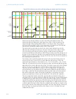
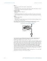
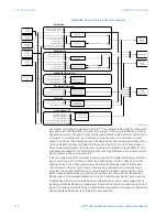
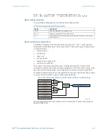
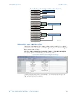
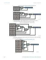
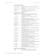
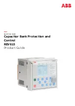
Figure 407: Using comparators to verify approximate equivalence
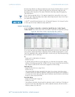
About automation timers
Unlike earlier versions of the D90
Plus
, automation timers are implemented like gates or
latches and not through the specific setting menus. Automation timers have the following
syntax:
TIMER (IN, PKP, DPO)
.
A
timer
accepts any digital input or the output of any logical operator as its
IN
parameter.
The timer output is asserted when its input is asserted for a time equal to or greater than
the
PKP
parameter. Likewise, the timer output will reset when its input has been reset for a
time equal to or greater than its
DPO
parameter.
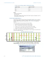
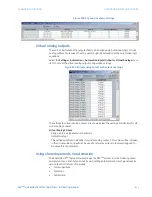
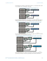
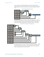
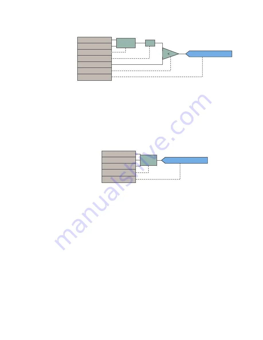
For example, the following logic produces an output that will pickup 10 seconds after
contact input F1 closes and will dropout 1 second after the contact opens.
Figure 408: Using an automation timer
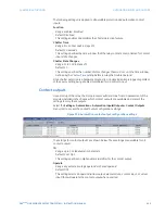
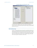
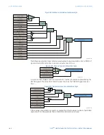
Virtual analogs can also be assigned to control the pickup and dropout of timers. In the
following example, two virtual analogs are used to define the pickup and dropout of two
different timers.
$&'5
65&,$506
65&,$506
68%D²E
D
E
68%
$%6
$%6
²
/(667+$1
$8792$92
$8792$92
%.5$21)
$7,0(5
$8792$92
$7,0(5
$&'5
$8792$9
,1
3.
'3

