16
D90
PLUS
LINE DISTANCE PROTECTION SYSTEM – INSTRUCTION MANUAL
DEVICE OVERVIEW
CHAPTER 2: PRODUCT DESCRIPTION
Front panel interface
An intuitive and easy-to-use color graphical display is provided in the D90
Plus
front panel.
The display provides easy access and visualization of device information, ranging from the
large display of metered values such as voltage, current, demand, energy, and sequence
components, to a comprehensive display of fault reports, sequence of events, and
transient recorded waveforms. The front panel interface also displays device health
information with critical and non-critical alarm status.
This advanced functionality allows the user to access comprehensive information without
having to navigate through conventional displays and keypads. Information is displayed
through two dedicated display panels. One serves as a digital annunciator and the other
reflects display and control functions.
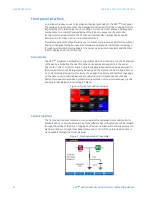
Annunciator
The D90
Plus
provides an embedded, configurable color LCD annunciator on the front panel
of the device, eliminating the need for LEDs and separate annunciators in the panel.
Any contact, direct, or remote input, or internally generated operand can be assigned to
the annunciator. Up to 288 targets may be assigned. The display can be configured for 12,
24, or 48 alarms per page to a maximum of 24 pages. A separate self-test message page
on the annunciator panel displays easy to understand error messages about device
health. This page also provides a graphical representation of the error messages, greatly
assisting in identifying and correcting problems.
Figure 6: Typical annunciator display
Control functions
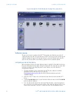
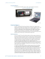
The front panel interface contains a mimic diagram that provides status and control for
breakers and up to disconnect switches. Many different bay configurations can be realized
through the setting of the device. Tagging of a device and substitution of device status can
also be carried out through front panel. Status and control of the autoreclose function is
also available through the mimic diagram.
Figure 7: Front panel control example


