630
D90
PLUS
LINE DISTANCE PROTECTION SYSTEM – INSTRUCTION MANUAL
THE D90
Plus
DISTANCE ELEMENTS
CHAPTER 15: THEORY OF OPERATION
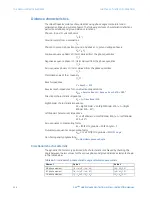
Distance characteristics
The relay shapes its distance characteristics using phase angle comparators and
estimated voltage and current phasors. The following distance characteristic definitions
pertain to all phase and ground distance functions.
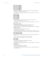
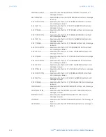
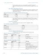
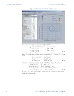
Phase A, B, and C current phasors
I
A
,
I
B
,
I
C
Ground current from a parallel line
I
G
Phase A to ground, phase B to ground, and phase C to ground voltage phasors
V
A
,
V
B
,
V
C
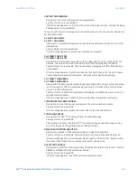
Positive-sequence phasor of ( ) term derived from the phase quantities
( )_1
Negative-sequence phasor of ( ) term derived from the phase quantities
( )_2
Zero-sequence phasor of ( ) term derived from the phase quantities
( )_0
Memorized value of the ( ) quantity
( )_M
Reach impedance
Z
=
Reach
∠
RCA
Reverse reach impedance for non-directional applications
Z
REV
=
Reverse Reach
∠
Reverse Reach RCA
+ 180°
Directional characteristic impedance
Z
D
= 1
∠
Directional RCA
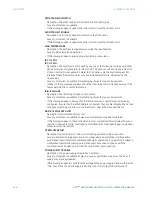
Right blinder characteristic impedance
Z
R
= Right Blinder × sin (Right Blinder RCA) × 1
∠
(Right
Blinder RCA – 90°)
Left blinder characteristic impedance
Z
L
= Left Blinder × sin (Left Blinder RCA) × 1
∠
(Left Blinder
RCA + 90°)
Zero-sequence compensating factor
K
0
= (Z0/Z1 Magnitude
∠
Z0/Z1 Angle) – 1
Mutual zero-sequence compensating factor
K
0
M
=
⅓
x Z0M/Z1 Magnitude
∠
Z0M/Z1 Angle
Non-homogeneity angle setting
Θ
=
Non-Homogeneous Angle
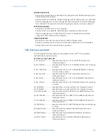
Directional mho characteristic
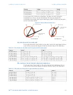
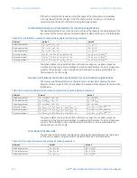
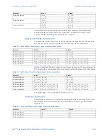
The dynamic 100% memory polarized mho characteristic is achieved by checking the
angle between the two values for the various phase and ground distance elements shown
in the table below.
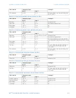
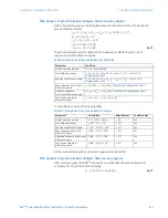
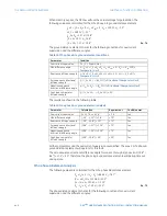
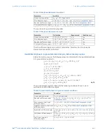
Table 46: Directional mho characteristic angle calculation parameters
Element
Value 1
Value 2
AB phase element
(
I
A
–
I
B
) ×
Z
– (
V
A
–
V
B
)
(
V
A
–
V
B
)_1M
BC phase element
(
I
B
–
I
C
) ×
Z
– (
V
B
–
V
C
)
(
V
B
–
V
C
)_1M
CA phase element
(
I
C
–
I
A
) ×
Z
– (
V
C
–
V
A
)
(
V
C
–
V
A
)_1M


