CHAPTER 7: PROTECTION
CONTROL ELEMENTS
D90
PLUS
LINE DISTANCE PROTECTION SYSTEM – INSTRUCTION MANUAL
359
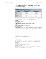
Select the
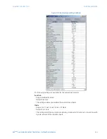
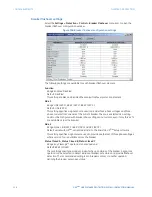
Settings > Protection > Control > Underfrequency
menu item to open the
underfrequency settings window.
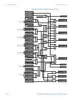
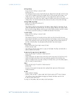
Figure 299: Underfrequency configuration settings
The following settings are available for each underfrequency element.
Function
Range: Enabled, Disabled
Default: Disabled
This setting enables and disables the underfrequency function.
Source
Range: LINE (SRC 1), BKR 1 (SRC 2), BKR 2 (SRC 3)
Default: LINE (SRC 1)
This setting selects the source for the signal to be measured. The element first checks for
a live phase voltage available from the selected source. If voltage is not available, the
element attempts to use a phase current. If neither voltage nor current is available, the
element will not operate, as it will not measure a parameter below the minimum voltage
or current setting.
Minimum Voltage/Current
Range: 0.10 to 1.25 pu in steps of 0.01
Default: 0.10 pu
This setting selects the minimum per-unit voltage or current level required to allow the
underfrequency element to operate. This threshold is used to prevent an incorrect
operation because there is no signal to measure.
Pickup
Range: 20.00 to 65.00 Hz in steps of 0.01
Default: 59.50 Hz
This setting specifies the pickup level for the underfrequency element. For example, if
the system frequency is 60 Hz and load shedding is required at 59.5 Hz, the setting will
be 59.50 Hz.
Pickup Delay
Range: 0.000 to 65.535 seconds in steps of 0.001
Default: 2.000 seconds
This setting specifies a time delay on pickup for the duration between the pickup and
operate output states of the underfrequency element.


