CHAPTER 8: AUTOMATION
AUTOMATION CONTROL
D90
PLUS
LINE DISTANCE PROTECTION SYSTEM – INSTRUCTION MANUAL
453
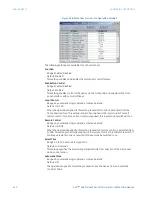
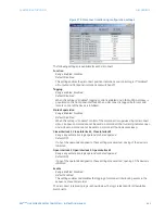
Dead Source Select
Range: None, LV1 and DV2, DV1 and LV2, DV1 or DV2, DV1 Xor DV2, DV1 and DV2
Default: LV1 and DV2
This setting selects the combination of dead and live sources that will bypass the
synchronism check function and permit the breaker to be closed when one or both of
the two voltages (
V
1
and
V
2
) are below the maximum voltage threshold. A dead or live
source is declared by monitoring the voltage level. Six options are available:
–
“None”: the dead source function is disabled
–
“LV1 and DV2”: live
V
1
and dead
V
2
–
“DV1 and LV2”: dead
V
1
and live
V
2
–
“DV1 or DV2”: dead
V
1
or dead
V
2
–
“DV1 Xor DV2”: dead
V
1
exclusive-or dead
V
2
(one source is dead and the other is
live)
–
“DV1 and DV2”: dead
V
1
and dead
V
2
Dead V1 Maximum Voltage
Range: 0.00 to 1.25 pu in steps of 0.01
Default: 0.30 pu
This setting specifies a maximum voltage magnitude for
V
1
in per-unit values. At values
less than this magnitude, the
V
1
voltage input used for synchrocheck will be considered
dead or de-energized.
Dead V2 Maximum Voltage
Range: 0.00 to 1.25 pu in steps of 0.01
Default: 0.30 pu
This setting specifies a maximum voltage magnitude for
V
2
in per-unit values. At values
less than this magnitude, the
V
2
voltage input used for synchrocheck will be considered
dead or de-energized.
Live V1 Minimum Voltage
Range: 0.00 to 1.25 pu in steps of 0.01
Default: 0.70 pu
This setting specifies a minimum voltage magnitude for
V
1
in per-unit values. At values
greater than this magnitude, the
V
1
voltage input used for synchrocheck will be
considered live or energized.
Live V2 Minimum Voltage
Range: 0.00 to 1.25 pu in steps of 0.01
Default: 0.70 pu
This setting specifies a minimum voltage magnitude for
V
2
in per-unit values. At values
greater than this magnitude, the
V
2
voltage input used for synchrocheck will be
considered live or energized.
Events
Range: Enabled, Disabled
Default: Enabled
This setting enables and disables the logging of synchrocheck events in the sequence of
events recorder.
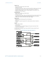
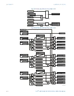
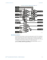
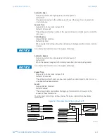
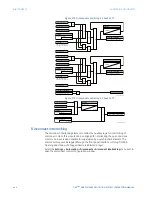
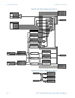
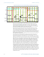
The logic for the synchrocheck element is illustrated below.

