


CHAPTER 11: METERING
PHASOR MEASUREMENT UNIT
D90
PLUS
LINE DISTANCE PROTECTION SYSTEM – INSTRUCTION MANUAL
537
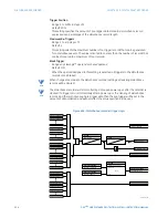
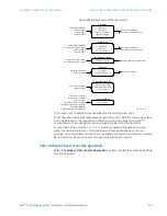
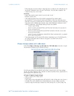
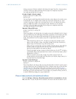
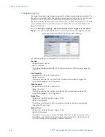
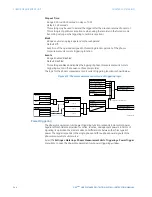
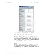
Figure 464: Phasor measurement unit communications configuration
The following settings are available for the communication port on each phasor
measurement unit.
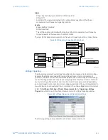
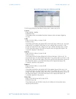
Type
Range: None, Network
Default: None
This setting specifies the first communication port for transmission of the phasor
measurement unit data. The three ports are configured under individual menus.
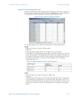
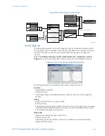
PHS-1, PHS-2, PHS-3,..., PHS-14
Range: Off, Va, Vb, Vc, Vx, Ia, Ib, Ic, Ig, V1, V2, V0, I1, I2, I0
Default: Off
These settings select synchrophasors to be transmitted from the superset of all
synchronized measurements. The available synchrophasor values are listed below.
–
Va: the first voltage channel, either Va or Vab.
–
Vb: the second voltage channel, either Vb or Vbc.
–
Vc: the third voltage channel, either Vc or Vca.
–
Vx: the fourth voltage channel.
–
Ia: phase A current, physical channel or summation as per the source settings.
–
Ib: phase B current, physical channel or summation as per the source settings.
–
Ic: phase C current, physical channel or summation as per the source settings.