CHAPTER 7: PROTECTION
PROTECTION FLEXLOGIC™
D90
PLUS
LINE DISTANCE PROTECTION SYSTEM – INSTRUCTION MANUAL
409
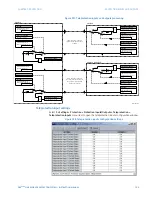
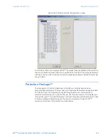
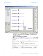
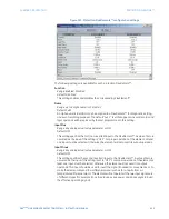
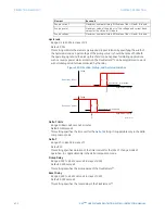
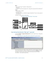
Figure 350: Protection FlexElements™ configuration settings
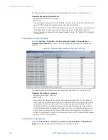
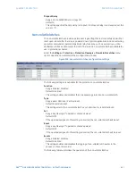
The following settings are available for each protection FlexElement™.
Function
Range: Enabled, Disabled
Default: Disabled
This setting enables and disables the corresponding FlexElement™.
Name
Range: up to 6 alphanumeric characters
Default: FxE 1
An alphanumeric identifier may be assigned to a FlexElement™ for diagnostic, setting,
and event recording purposes. The default “FxE 1” text that appears in event records and
logic operands will be replaced by the text programmed in this setting.
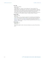
Input Plus
Range: any analog actual value parameter or OFF
Default: OFF
This setting specifies the first (non-inverted) input to the FlexElement™. A value of zero is
assumed as the input if this setting is “OFF”. For proper operation of the element, at least
one input must be selected. Otherwise, the element will not assert its output operands.
Input Minus
Range: any analog actual value parameter or OFF
Default: OFF
This setting specifies the second (inverted) input to the FlexElement™. A value of zero is
assumed as the input if this setting is set to “OFF”. For proper operation of the element at
least one input must be selected. Otherwise, the element will not assert its output
operands. This input should be used to invert the signal if needed for convenience, or to
make the element respond to a differential signal such as for a top-bottom oil
temperature differential alarm. The element will not operate if the two input signals are
of different types (for example if one tries to use active power and phase angle to build
the effective operating signal).

