CHAPTER 6: COMMUNICATIONS
IEC 61850 COMMUNICATIONS
D90
PLUS
LINE DISTANCE PROTECTION SYSTEM – INSTRUCTION MANUAL
131
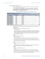
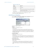
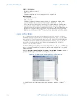
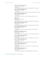
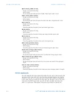
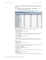
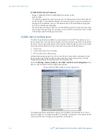
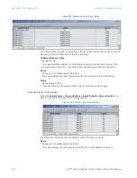
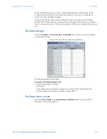
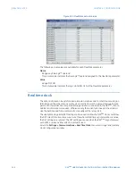
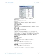
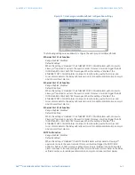
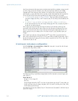
Figure 105: IEC 61850 GGIO4 analog configuration
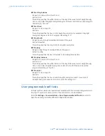
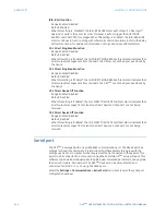
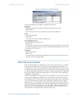
The following settings are available.
IEC 61850 GGIO4 Analogs
Range: 4 to 32 in steps of 4
Default: 4
This setting specifies how many analog data points will exist in GGIO4. When this value is
changed, the D90
Plus
must be rebooted to allow the GGIO4 logical node to be re-
instantiated and contain the newly configured number of analog points.
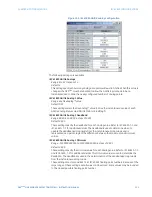
IEC 61850 GGIO4 Analog 1 Value
Range: any FlexAnalog™ value
Default: OFF
These settings select the FlexAnalog™ value to drive the instantaneous value of each
GGIO4 analog status value (GGIO4.MX.AnIn1.instMag.f).
IEC 61850 GGIO4 Analog 1 Deadband
Range: 0.000 to 100.000 in steps of 0.001
Default: 0.000
These settings specify the deadband for each analog value. Refer to IEC 61850-7-1 and
IEC 61850- 7-3 for additional details. The deadband is used to determine when to
update the deadbanded magnitude from the instantaneous magnitude and is
represented as a percentage of the difference between the maximum and minimum
values.
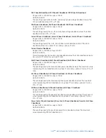
IEC 61850 GGIO4 Analog 1 Minimum
Range: –1000000000.000 to 1000000000.000 in steps of 0.001
Default: 0.000
These settings specify the minimum value for each analog value. Refer to IEC 61850-7-1
and IEC 61850-7-3 for additional details. This minimum value is used to determine the
deadband. The deadband is used in the determination of the deadbanded magnitude
from the instantaneous magnitude.
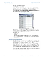
These settings are stored as IEEE 754 / IEC 60559 floating point numbers. Because of the
large range of these settings, not all values can be stored. Some values may be rounded
to the closest possible floating point number.

