CHAPTER 11: METERING
METERED VALUES
D90
PLUS
LINE DISTANCE PROTECTION SYSTEM – INSTRUCTION MANUAL
563
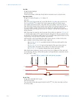
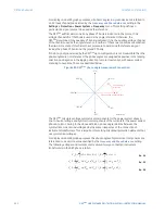
The following voltages and currents are measured for wye-connected instrument
transformers in the ACB phase rotation.
Eq. 57
Eq. 58
Eq. 59
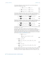
The following voltages and currents are measured for delta-connected instrument
transformers in the ABC phase rotation. The zero-sequence voltage (V_0) not measurable
under the delta connection of instrument transformers and is defaulted to zero.
Eq. 60
Eq. 61
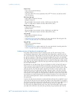
The following voltages and currents are measured for delta-connected instrument
transformers in the ACB phase rotation. The zero-sequence voltage (V_0) is not measurable
under the delta connection of instrument transformers and is defaulted to zero.
Eq. 62
Eq. 63
In the above equations,
a
represents phase rotation operator that rotates a phasor vector
forward by 120° (
a
= 1
∠
120°).
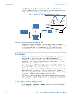
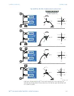
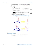
For example, consider a wye connected VT with the following system voltages (in
secondary volts):
V
AG
= 13.9 V
∠
0°,
V
BG
= 76.2 V
∠
–125°,
V
CG
= 79.7 V
∠
–250°,
V
AB
= 84.9 V
∠
–
313°,
V
BC
= 138.3 V
∠
–97°, and
V
CA
= 85.4 V
∠
–241°. For simplicity, the power system
voltages are phase-referenced to
V
AG
. However, any value can be chosen as a reference. It
is important to remember that displayed values are always referenced as to the voltage
specified by the
Frequency and Phase Reference
setting.
Eq. 64
Eq. 65
Eq. 66
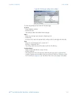
As another example, consider a delta connected VT with the following system voltages (in
secondary volts):
V
AB
= 84.9 V
∠
0°,
V
BC
= 138.3 V
∠
–144°, and
V
CA
= 85.4 V
∠
–288°. For
simplicity, the power system voltages are phase-referenced to
V
AB
. However, any value
B
,
B
9
&
%
$
&*
%*
$*
,
,
,
9
9
9
B
,
B
9
&
%
$
&*
%*
$*
D,
,
D
,
D9
9
D
9
B
,
B
9
&
%
$
&*
%*
$*
,
D
D,
,
9
D
D9
9
B
,
B
9
&
%
$
&$
%&
$%
,
D
D,
,
9
D
D9
9
B
,
B
9
&
%
$
&$
%&
$%
D,
,
D
,
D9
9
D
9
B
,
B
9
&
%
$
&$
%&
$%
D,
,
D
,
D9
9
D
9
B
,
B
9
&
%
$
&$
%&
$%
,
D
D,
,
9
D
D9
9
²
²
B
9
&*
%*
$*
9
9
9
B
9
&*
%*
$*
9
D
D9
9
B
9
&*
%*
$*
D9
9
D
9

