CHAPTER 8: AUTOMATION
AUTOMATION LOGIC
D90
PLUS
LINE DISTANCE PROTECTION SYSTEM – INSTRUCTION MANUAL
483
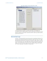
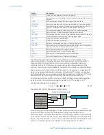
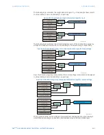
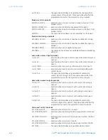
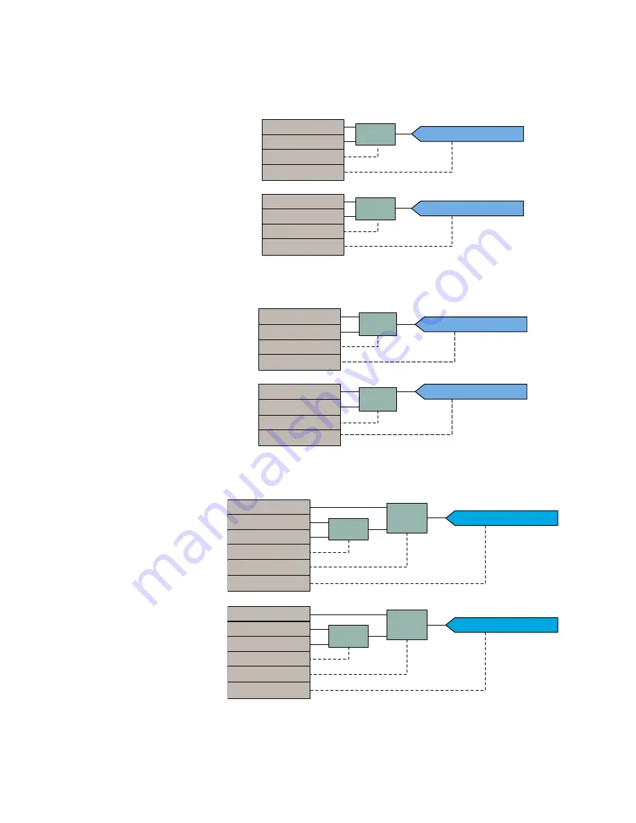
The following logic calculates the magnitude and angle of
I
1
×
Z
and assigns these results
to virtual analog 2 and virtual analog 3, respectively.
Figure 412: Magnitude and angle calculation logic for
I
1
×
Z
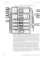
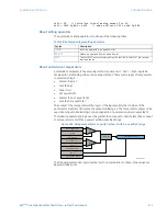
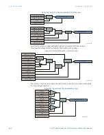
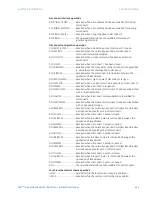
The following logic calculates the real and imaginary parts of the local positive-sequence
voltage and assigns these results to virtual analog 4 and virtual analog 5, respectively.
Figure 413: Real and imaginary component calculation logic for local voltage
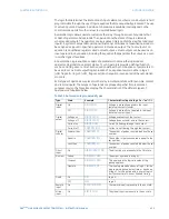
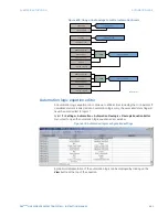
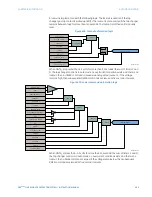
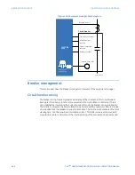
Next, the real and imaginary components of the remote voltage is calculated and assigned
to virtual analog 6 and virtual analog 7, respectively.
Figure 414: Real and imaginary component calculation logic for remote voltage
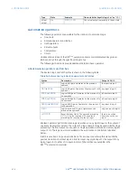
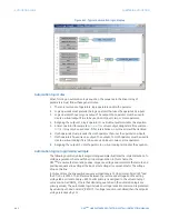
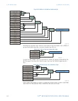
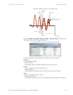
The magnitude of the remote voltage is calculated next and assigned to virtual analog 9.
Note that virtual analog 8 is used as an intermediate value in the automation logic.
/,1(,0$*
08/
08/
,î=0$*9$
,î=0$*9$
/,1(,$1*/(
$''
$''
,î=$1*9$
,î=$1*9$
$&'5
/,1(9$1*/(
5($/
5($/
9B5($/9$
9B5($/9$
$&'5
/,1(992/7$*(
,0$*
/,1(9$1*/(
9B,0$*9$
/,1(992/7$*(
,0$*
9B,0$*9$
$&'5
9B5($/9$
,î=0$*9$
,î=$1*9$
5($/
68%
95(027(B5($/9$
5($/
68%D²E
D
E
95(027(B5($/9$
9B,0$*9$
,î=0$*9$
,î=$1*9$
,0$*
68%
95(027(B,0$*9$
,0$*
68%D²E
D
E
95(027(B,0$*9$

