CHAPTER 7: PROTECTION
GROUPED PROTECTION ELEMENTS
D90
PLUS
LINE DISTANCE PROTECTION SYSTEM – INSTRUCTION MANUAL
285
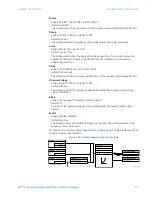
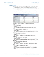
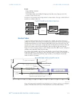
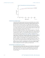
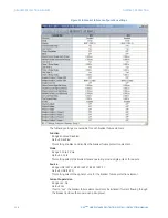
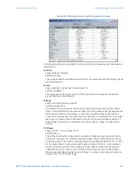
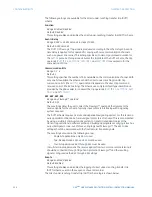
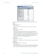
Figure 245: Wattmetric ground fault configuration window
The following settings are available for each wattmetric zero-sequence directional ground
fault element.
Function
Range: Enabled, Disabled
Default: Disabled
This setting enables and disables the wattmetric zero-sequence directional ground fault
protection element.
Source
Range: LINE (SRC 1), BKR 1 (SRC 2), BKR 2 (SRC 3)
Default: LINE (SRC 1)
This setting selects the signal source for the wattmetric zero-sequence directional
ground fault protection element.
Voltage
Range: Calculated VN, Measured VX
Default: Calculated VN
The wattmetric zero-sequence directional ground fault element uses neutral voltage
(that is, three times the zero-sequence voltage). This setting allows selecting between the
internally calculated neutral voltage, or externally supplied voltage (broken delta VT
connected to the auxiliary channel bank of the relay). When the latter selection is made,
the auxiliary channel must be identified by the user as a neutral voltage under the VT
bank settings. This element will operate only if the auxiliary voltage is configured as
neutral.
OV Pickup
Range: 0.02 to 1.10 pu in steps of 0.01
Default: 0.20 pu
This setting specifies the minimum zero sequence voltage supervising the directional
power measurement. This threshold should be higher than possible unbalance during
normal operation of the system. Typically, this setting would be selected at 0.1 to 0.2 pu
for the ungrounded or resonant grounded systems, and at 0.05 to 0.1 pu for solidly or
resistor-grounded systems. When using externally supplied voltage via the auxiliary
voltage channel, 1 pu is the nominal voltage of this channel as per VT bank settings.
When using internally calculated neutral voltage, 1 pu is the nominal phase to ground
voltage as per the VT bank settings.

