


CHAPTER 6: COMMUNICATIONS
IEC 61850 COMMUNICATIONS
D90
PLUS
LINE DISTANCE PROTECTION SYSTEM – INSTRUCTION MANUAL
129
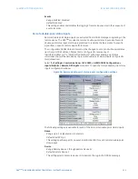
GGIO1 status configuration
The GGIO1 logical node provides access to as many 128 digital status points and
associated timestamps and quality flags. It is intended that clients use GGIO1 to access
digital status values from the D90
Plus
. Configuration settings are provided to select the
number of digital status indications available in GGIO1 (8 to 128) and select logic operands
to drive the status of the GGIO1 status indications. Clients can utilize the IEC 61850
buffered and unbuffered reporting features available from GGIO1 to build sequence of
events (SOE) logs and HMI display screens. Buffered reporting should generally be used for
SOE logs since the buffering capability reduces the chances of missing data state changes.
Unbuffered reporting should generally be used for local status display.
Select the
Settings > Communications > IEC 61850 > GGIO1 Status Configuration
menu
item to open the GGIO1 status configuration window.
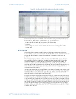
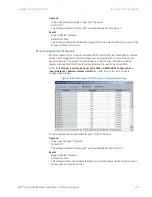
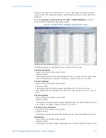
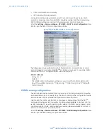
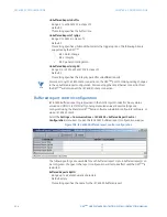
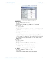
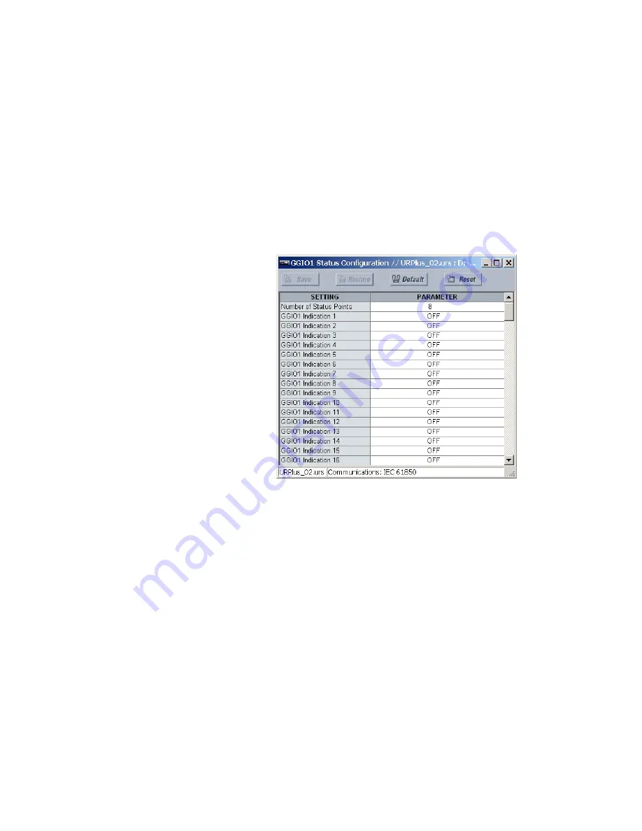
Figure 103: IEC 61850 GGIO1 status configuration
The following settings are available.
Number of Status Points
Range: 8 to 128 in steps of 8
Default: 8
This setting specifies the number of “Ind” points (single point status indications)
instantiated in the GGIO1 logical node. Changes to this setting will not take effect until
the D90
Plus
is restarted.
GGIO1 Indication 1, GGIO1 Indication 2,..., GGIO1 Indication 128
Range: any logic operand
Default: OFF
These settings assign logic operands to represent GGIO1 status indications.
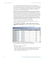
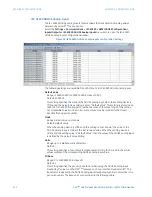
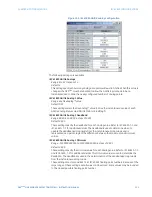
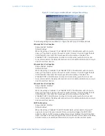
GGIO2 control configuration
The GGIO2 logical node provides access to the D90
Plus
protection virtual inputs. Protection
virtual inputs are single-point control (binary) values that can be written by clients. They are
generally used as control inputs. GGIO2 provides access to protection virtual inputs
through the IEC 61850 standard control model (ctlModel) services:
•
Status only.