
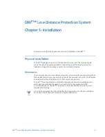


CHAPTER 3: INSTALLATION
ELECTRICAL INSTALLATION
D90
PLUS
LINE DISTANCE PROTECTION SYSTEM – INSTRUCTION MANUAL
49
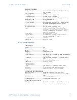
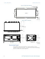
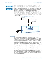
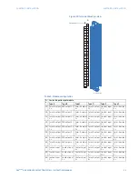
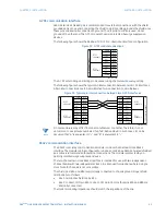
Figure 19: Rear terminal view
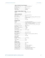
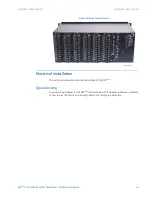
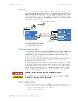
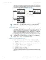
Electrical installation
This section describes the electrical installation of the D90
Plus
.
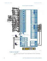
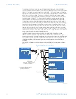
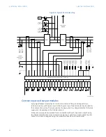
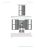
Typical wiring
A typical wiring diagram for the D90
Plus
is shown below. This diagram provides an example
of how to wire the device. Actual wiring will vary according to application.
$&'5