382
D90
PLUS
LINE DISTANCE PROTECTION SYSTEM – INSTRUCTION MANUAL
PROTECTION INPUTS AND OUTPUTS
CHAPTER 7: PROTECTION
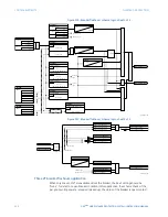
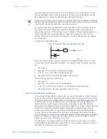
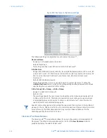
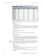
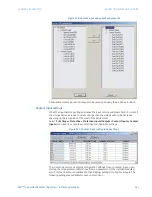
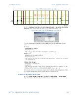
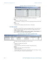
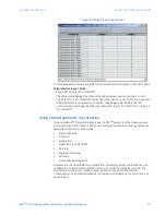
Figure 320: Protection virtual inputs configuration settings
The following settings are available for each protection virtual input. The default values
shown are for virtual input 1.
Function
Range: Enabled, Disabled
Default: Disabled
If this setting is “Disabled”, the virtual input will be forced to off (logic 0) regardless of any
attempt to alter the input. If set to “Enabled”, the input operates as shown on the logic
diagram and generates output logic operands in response to received input signals and
the applied settings.
ID
Range: up to 12 alphanumeric characters
Default: Virt Ip 1
This setting specifies an identifier that may be assigned to each virtual input.
Type
Range: Self-Reset, Latched
Default: Latched
There are two types of operation: self-reset and latched. If this settings is “Self-Reset”, the
output operand will be asserted (logic 1) for only one evaluation of the protection
FlexLogic™ equations and then return to 0 when the input signal transits from off to on.
If set to “Latched”, the virtual input sets the state of the output operand to the same
state as the most recent received input.
NOTE
NOTE:
The self-reset operating mode generates an output operand for a single evaluation of
FlexLogic™ equations. If the operand is to be used anywhere other than internally in an
automation logic equation, it will likely have to be lengthened in time. A FlexLogic™ timer
with a delayed reset can perform this function.
Events
Range: Enabled, Disabled
Default: Disabled
If this setting is “Enabled”, every change in the protection virtual input state will trigger
an event in the sequence of events recorder.
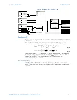
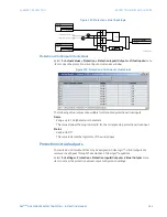
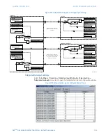
The protection virtual input logic is shown below. The logic is identical for all protection
virtual inputs.

