132
D90
PLUS
LINE DISTANCE PROTECTION SYSTEM – INSTRUCTION MANUAL
IEC 61850 COMMUNICATIONS
CHAPTER 6: COMMUNICATIONS
IEC 61850 GGIO4 Analog 1 Maximum
Range: –1000000000.000 to 1000000000.000 in steps of 0.001
Default: 0.000
These settings specify the maximum value for each analog value. Refer to IEC 61850-7-1
and IEC 61850-7-3 for additional details. This maximum value is used to determine the
deadband. The deadband is used in the determination of the deadbanded magnitude
from the instantaneous magnitude.
These settings are stored as IEEE 754 / IEC 60559 floating point numbers. Because of the
large range of these settings, not all values can be stored. Some values may be rounded
to the closest possible floating point number.
GGIO5 control configuration
The GGIO5 logical node is available to provide access to the D90
Plus
automation virtual
inputs. Automation virtual inputs are single-point control (binary) values that can be written
by clients. They are generally used as control inputs. GGIO5 provides access to automation
virtual inputs through the IEC 61850 standard control model (ctlModel) services:
•
Status only.
•
Direct control with normal security.
•
SBO control with normal security.
Configuration settings select the control model for each point. Each automation virtual
input used through GGIO5 should be enabled and the corresponding SPSCO ctlModel
setting programmed to the appropriate control configuration.
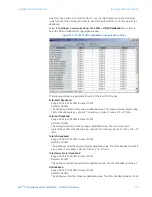
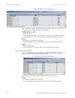
Select the
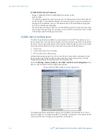
Settings > Communications > IEC 61850 > GGIO5 Control Configuration
menu
item to open the GGIO5 control configuration window.
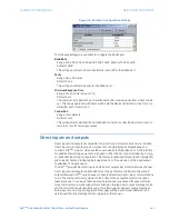
Figure 106: IEC 61850 GGIO5 control configuration
The following setting is available for each of the 128 GGIO5 control points. Each control
point is mapped to a corresponding D90
Plus
automation virtual input. For example, GGIO5
control point SPCSO 3 is mapped to automation virtual input 3.


