background image


Access Power Distribution Boards 

Manual 


Features: 


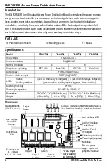
For 12/24 VAC/VDC operation 


Each output individually fused 


Each output can operate in both fail-safe 
and fail-secure modes  


Each output individually controlled 


Individual output relays (10A@24VDC) 


Output fuses rated at 3.0A ([email protected])  


Individual status LEDs for each output and 
for emergency input 


Auxiliary supervision relay (1A@28VDC) 


Equipped with dry and wet trigger inputs 
(blade versions only) 


Includes auxiliary interface to enable 
emergency egress, alarm monitoring, or to 
trigger other devices 


Includes auxiliary interface disconnect, 
individually selectable for each output 


Compatible with ENFORCER Access 
Control Power Supplies  

Model 

Output Fuse 

No. of 

Outputs 

Main 
Fuse 

Type 

Rating 

PD-4PTQ 

PTC 

2.5A 

10A 

PD-4BTQ 

Blade 

3.0A 

10A 

PD-8PTQ 

PTC 

2.5A 

10A 

PD-8BTQ 

Blade 

3.0A 

10A 


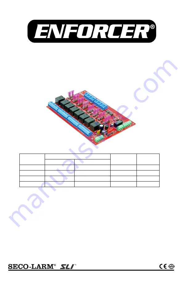
PD-8BTQ shown 

Summary of Contents for SLI ENFORCER PD-4PTQ

Page 1: ...d for emergency input Auxiliary supervision relay 1A 28VDC Equipped with dry and wet trigger inputs blade versions only Includes auxiliary interface to enable emergency egress alarm monitoring or to t...

Page 2: ...t DPDT 1A 28VDC LEDs Status 4 red on when relay is energized 8 red on when relay is energized Auxiliary Interface 1 green on when auxiliary input is triggered alarm condition Operating humidity 0 95 O...

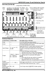
Page 3: ...INTERFACE AUX OUTPUT AUX INTERFACE 10A 250V POWER CONTROL Terminal Group Terminal Labels Description of Use or Function Power 12 24 VAC VDC Power supply required Control Can be connected to a second...

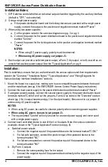
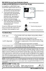
Page 4: ...the board in a supply box making sure to use compatible spacers between the board and the metal back see pg 8 for ENFORCER Access Control Power Supply instructions 2 Connect the main power supply to...

Page 5: ...cess control panel open collector s common negative to the power distribution board s input terminal marked GND 6 Connect an Auxiliary Interface Control Panel AICP to the power distribution board s Au...

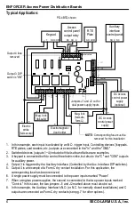
Page 6: ...utputs are connected to the In and the GND 2 Switched devices outputs 1 4 include both fail safe and fail secure examples 3 A keypad is connected both to control the electric strike but also to the C...

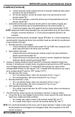
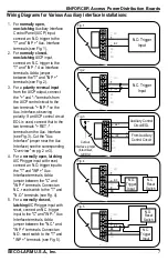
Page 7: ...a jumper between the T and INP terminals see Fig 2 3 For a polarity reversal input from the AICP output connect the and terminals from the AICP control circuit to the two terminals INP on the Aux Int...

Page 8: ...n is limited to the repair or replacement of any defective part if the unit is returned transportation prepaid to SECO LARM This Warranty is void if damage is caused by or attributed to acts of God ph...

Reviews: