CHAPTER 7: PROTECTION
PROTECTION INPUTS AND OUTPUTS
D90
PLUS
LINE DISTANCE PROTECTION SYSTEM – INSTRUCTION MANUAL
389
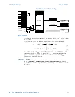
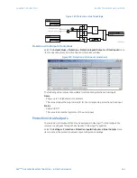
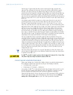
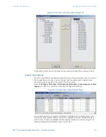
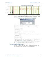
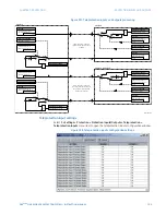
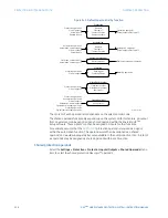
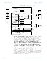
Figure 328: Chatter detection example
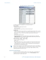
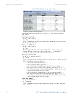
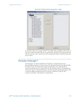
Select the
Settings > Protection > Protection Inputs/Outputs > Contact Inputs > Chatter
Detection
menu item to access the contact input chatter detection settings.
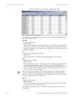
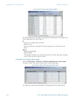
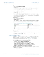
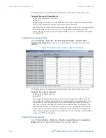
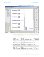
Figure 329: Contact input chatter detection configuration
The following settings are applied to all available protection and automation contact
inputs.
Function
Range: Enabled, Disabled
Default: Disabled
This setting enables and disables the chatter detection feature.
Chatter Time
Range: 1 to 100 seconds in steps of 1
Default: 10 seconds
This setting specifies the time window that the relay contacts are monitored for contact
input state changes.
Chatter State Changes
Range: 10 to 100 in steps of 1
Default: 30
This setting specifies the number of state changes that must occur in the time window
defined by the
Chatter Time
setting before issuing the trouble operand.
Since chatter detection is a hardware diagnostic, a trouble indication is logged regardless
of the
Events
setting being enabled or disabled for a particular input.
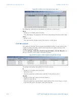
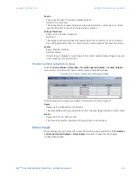
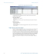
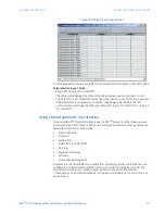
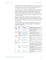
Protection contact input actual values
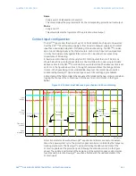
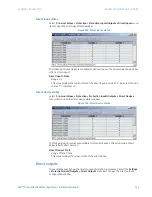
Select the
Actual Values > Protection > Protection Inputs/Outputs > Contact Inputs
menu item to open the protection contact input actual values window.
2))
21
V
&KDWWHU7LPH
,QSXW
YROWDJH
,QSXW
WURXEOH
$&'5

