144
D90
PLUS
LINE DISTANCE PROTECTION SYSTEM – INSTRUCTION MANUAL
SERIAL PORT
CHAPTER 6: COMMUNICATIONS
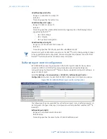
IRIG-B Fail Function
Range: Enabled, Disabled
Default: Enabled
When this setting is “Disabled”, the IRIG-B FAILURE alarm will not assert a FlexLogic™
operand or write to the event recorder. Moreover, it will not trigger the ANY MINOR
ALARM or ANY SELF-TEST messages. When this setting is “Enabled”, the IRIG-B FAILURE
alarm continues to function along with other major and minor alarms. Refer to the
Relay
self-tests
section in for additional information on major and minor self-test alarms.
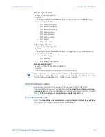
Ch 1 Direct Ring Break Function
Range: Enabled, Disabled
Default: Disabled
When this setting is “Enabled”, the CH1 DIRECT RING BREAK self-test alarm indicates that
direct output messages sent from channel 1 the D90
Plus
are not being received back by
the device.
Ch 2 Direct Ring Break Function
Range: Enabled, Disabled
Default: Disabled
When this setting is “Enabled”, the CH2 DIRECT RING BREAK self-test alarm indicates that
direct output messages sent from channel 2 the D90
Plus
are not being received back by
the device.
Ch 1 Direct Device Off Function
Range: Enabled, Disabled
Default: Disabled
When this setting is “Enabled”, the CH1 DIRECT DEVICE OFF self-test alarm indicates that
direct output messages from at least one direct device on channel 1 are not being
received.
Ch 2 Direct Device Off Function
Range: Enabled, Disabled
Default: Disabled
When this setting is “Enabled”, the CH2 DIRECT DEVICE OFF self-test alarm indicates that
direct output messages from at least one direct device on channel 2 are not being
received.
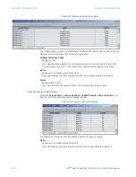
Serial port
The D90
Plus
is equipped with one serial RS485 communication port. The RS485 port has
settings for baud rate and parity. It is important that these parameters agree with the
settings used on the computer or other equipment that is connected to these ports. This
ports may be connected to a computer running the EnerVista UR
Plus
Setup software. This
software can download and upload setting files, view measured parameters, and upgrade
the device firmware. A maximum of 32 D90
Plus
devices can be daisy-chained and
connected to a DCS, PLC, or PC using the RS485 port.
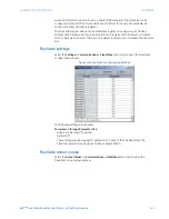
Select the
Settings > Communications > Serial Ports
menu item to open the serial port
configuration window.

