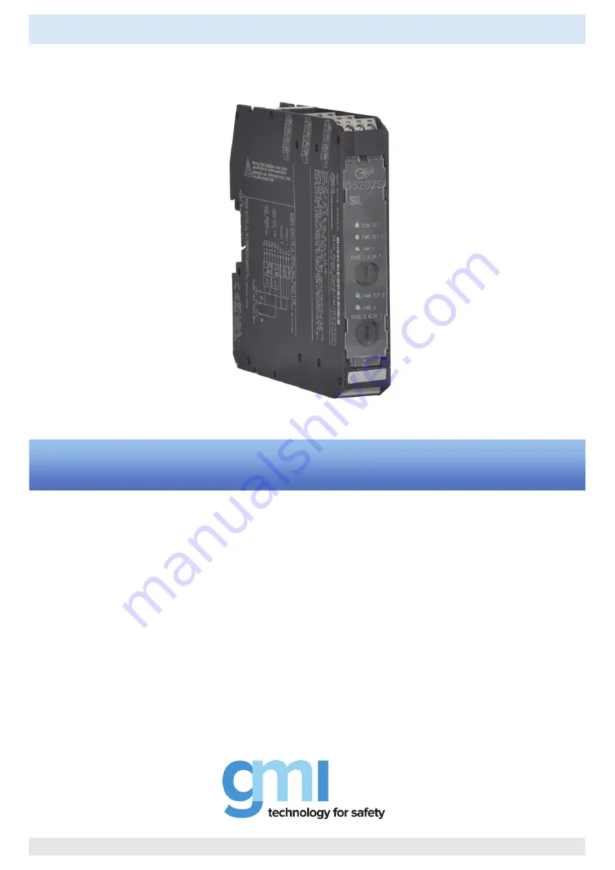
D5202S
- 4 A, 24 Vdc, SIL 3 Power Distribution and Diagnostic Module
G.M. International ISM0177-4
4 A, 24 Vdc, SIL 3 Power Distribution
and Diagnostic Module DIN-Rail,
Model D5202S
INSTRUCTION & SAFETY MANUAL
Page 1: ...02S 4 A 24 Vdc SIL 3 Power Distribution and Diagnostic Module G M International ISM0177 4 4 A 24 Vdc SIL 3 Power Distribution and Diagnostic Module DIN Rail Model D5202S D5202S INSTRUCTION SAFETY MANU...
Page 2: ...rtificate No C IS 224248 01 SIL 3 conforms to IEC61508 2010 Ed 2 T V Certificate No C IS 236198 09 SIL 3 Functional Safety Certificate conforms to IEC61508 2010 Ed 2 for Management of Functional Safet...
Page 3: ...ATEX IECEx UKR TR n 898 TUV Certifications T V Functional Safety Certification Type Approval Certificate DNV and KR for maritime applications Simplified installation on beginning end or both sides of...
Page 4: ...AREA ZONE 2 GROUP IIC T4 9 10 11 12 MODEL D5202S F Power and Fault Bus Power Supply 1 3 NC 2 NO Common Fault Output 1oo2 Power Fault 1 CM 7 NC 6 NO 5 CM Power Supply 2 Note In case of single power su...
Page 5: ...ble describes the OFF operation absence of supply on Power Bus and the ON operation presence of 20 30 Vdc supply on Power Bus of the D5202S according to the OFF ON state of each Power Supply source al...
Page 6: ...erefore considering all diagnostic functions enabled the cumulative fault diagnostic functionality is described by the following table where the status open or closed of Common Fault output contact is...
Page 7: ...the contact maximum rating 5 A 250 Vac 1250 VA 5 A 250 Vdc 175 W resistive load To prevent relay contacts from damaging connect an external protection fuse or similar chosen according to the relay br...
Page 8: ...detection on power supply 2 4 Operation with disabled cumulative fault detection DIP switch configurations 1 2 3 4 ON 5 6 7 8 OFF OFF OFF ON ON ON OFF OFF 1 2 3 4 ON 5 6 7 8 OFF OFF OFF ON ON ON OFF O...