7-43
1
Before Using the Products
2
Preparat
on
3
Connect
on
4
Setup
5
Ad
ustment
6
When
n T
roub
e
7
Supp
ement
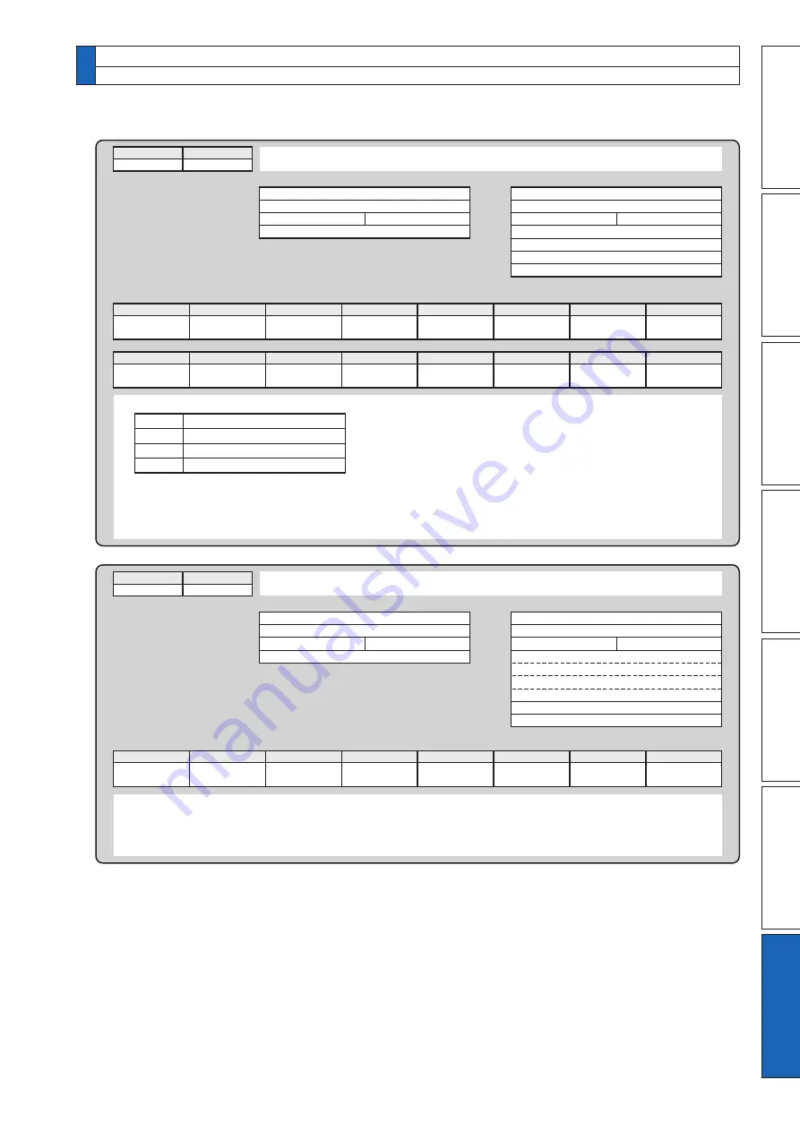
• Read out of command pulse counter
• Control modes are defined as follows.
Position control mode
Velocity control mode
Torque control mode
Full-closed control mode
command
2
mode
1
Reception data
0
axis
checksum
2
1
Error code
Transmission data
• Module returns the present position in absolute coordinates from the starting point. (Total sum of accumulated
command pulses)
• Counter value in 32 bit.
• Counter value will be "–" for negative direction and "+" for positive direction.
bit7
0 : Normal
1 : Error
6
5
Command error
4
RS485 error
3
2
1
0
5
axis
counter value L
H
error code
checksum
2
1
command
2
mode
0
• Read out of status
Reception data
0
axis
checksum
2
0
Error code
Transmission data
• positive direction/negative direction running : This becomes 1 when motor speed (after converted to r/min) is positive
(positive direction) or negative (negative direction).
• Slower than DB permission : This becomes 1 when motor speed (after converted to r/min) is below 30 r/min.
• Torque in-limit : This becomes 1 when torque command is limited by analog input or parameter.
bit7
0 : Normal
1 : Error
6
5
Command error
4
RS485 error
3
2
1
0
status
bit7
6
5
4
3
Positive direction
running
2
Negative direction
running
1
Slower than DB
permission
0
Torque in-limit
3
axis
control mode
status
error code
checksum
2
0
0
1
2
3
4. Communication
Details of Communication Command
Buy: www.ValinOnline.com | Phone 844-385-3099 | Email: [email protected]


