12 DATA USED FOR POSITIONING CONTROL
12.3 Basic Setting
395
12
[Pr.18] M code ON signal output timing
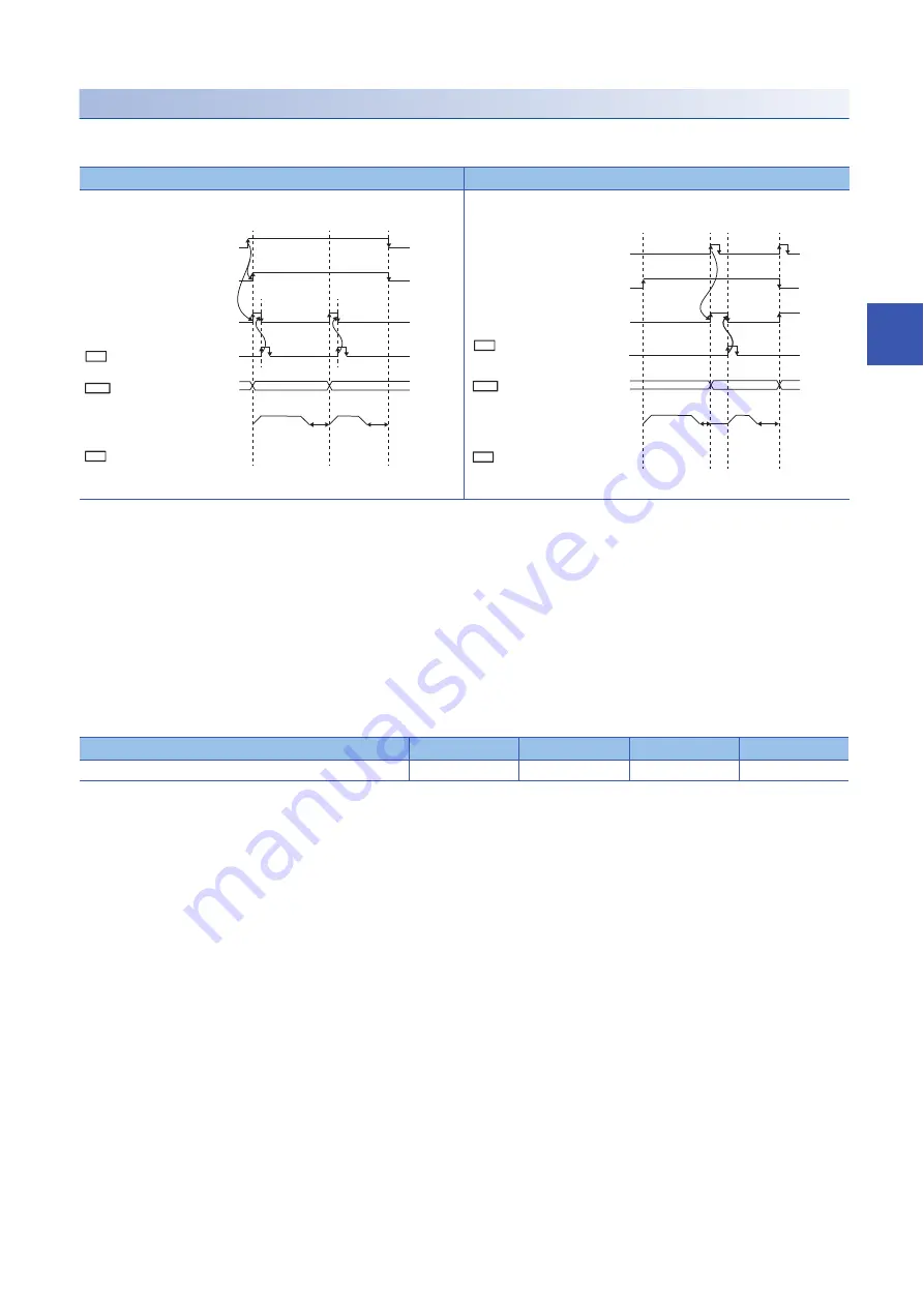
Set the timing of outputting the M code ON signal.
Select either the WITH mode or the AFTER mode as timing of outputting the M code ON signal.
• An M code is a number between 0 and 65535 that can be assigned to each positioning data (shape).
• Programs can be coded to read the M code from [Md.25] Valid M code whenever the M code ON signal [X4, X5, X6, X7]
turns on so that a command for sub works such as clamping, drilling, and tool change corresponding to the M code can be
issued.
• When the AFTER mode is set in the speed control, the M code is not output and the M code ON signal [X4, X5, X6, X7] is
not turned on.
• The M code ON signal output timing can be set for each positioning data with the positioning option ([Da.27] M code ON
signal output timing) of the positioning data.
■
Buffer memory address
The following table shows the buffer memory address of this area.
■
Default value
The default value is 0: WITH mode for all the axes.
WITH mode (setting value: 0)
AFTER mode (setting value: 1)
An M code is output and the M code ON signal [X4, X5, X6, X7] is turned on
when a positioning operation starts.
An M code is output and the M code ON signal [X4, X5, X6, X7] is turned on
when a positioning operation completes.
Buffer memory name
Axis 1
Axis 2
Axis 3
Axis 4
[Pr.18] M code ON signal output timing
27
177
327
477
m1
m2
Cd.7
Da.1
Md.25
*
*
01 (continuous)
00 (end)
Positioning start signal
[Y10, Y11, Y12, Y13]
BUSY signal
[XC, XD, XE, XF]
Positioning
M code ON signal
[X4, X5, X6, X7]
M code ON signal OFF request
[1504, 1604, 1704, 1804]
Operation pattern
Valid M code
*: m1 and m2 indicate set M codes.
m1
m2
Cd.7
Da.1
Md.25
*
*
*: m1 and m2 indicate set M codes.
01 (continuous)
00 (end)
Positioning complete signal
[X14, X15, X16, X17]
BUSY signal
[XC, XD, XE, XF]
Positioning
M code ON signal
[X4, X5, X6, X7]
M code ON signal OFF request
[1504, 1604, 1704, 1804]
Operation pattern
Valid M code
Содержание MELSEC iQ-R RD75P4
Страница 1: ...MELSEC iQ R Positioning Module User s Manual Application RD75P2 RD75P4 RD75D2 RD75D4 ...
Страница 2: ......
Страница 13: ...11 MEMO ...
Страница 19: ...17 CONTENTS INDEX 588 REVISIONS 592 WARRANTY 593 TRADEMARKS 594 ...
Страница 498: ...496 13 PROGRAMMING 13 2 List of Labels Used ...
Страница 503: ...13 PROGRAMMING 13 4 Program Example 501 13 ...
Страница 511: ...13 PROGRAMMING 13 4 Program Example 509 13 Torque change program Step operation program Skip program ...
Страница 512: ...510 13 PROGRAMMING 13 4 Program Example Teaching program Continuous operation interrupt program ...
Страница 513: ...13 PROGRAMMING 13 4 Program Example 511 13 Target position change program Absolute position restoration program ...
Страница 514: ...512 13 PROGRAMMING 13 4 Program Example Restart program Parameter data initialization program ...
Страница 515: ...13 PROGRAMMING 13 4 Program Example 513 13 Flash ROM write program Error reset program ...
Страница 516: ...514 13 PROGRAMMING 13 4 Program Example Stop program ...
Страница 565: ...APPENDICES Appendix 4 Operation Examples of When the Remote Head Module Is Mounted 563 A ...
Страница 568: ...566 APPENDICES Appendix 4 Operation Examples of When the Remote Head Module Is Mounted Common program ...
Страница 584: ...582 APPENDICES Appendix 4 Operation Examples of When the Remote Head Module Is Mounted Restart program ...
Страница 587: ...APPENDICES Appendix 4 Operation Examples of When the Remote Head Module Is Mounted 585 A Stop program ...
Страница 597: ......


