7 CONTROL SUB FUNCTIONS
7.5 Functions that Change Control Details
245
7
• If the speed is changed during the deceleration by a stop command or during the automatic deceleration in the positioning
control, Deceleration/stop speed change (Warning code: 0990H) occurs and the speed cannot be changed.
• When the value set in [Cd.14] New speed value exceeds the one in [Pr.8] Speed limit value, Speed limit value over
(Warning code: 0991H) occurs and the speed is controlled with [Pr.8] Speed limit value.
• To change the speed during the interpolation control, configure the required setting in the reference axis.
• To change the speed successively, set 10ms or longer as the interval between each speed change. (If the interval between
the speed changes is short, [Cd.15] Speed change request may not be accepted properly.)
• When a speed change is requested simultaneously to multiple axes, the speed change is performed one by one. Therefore,
the start timing of the speed change is different for each axis.
• During the machine OPR, the speed cannot be changed by setting 0 to [Cd.14] New speed value. The speed change
request is ignored.
• Deceleration start flag is not turned on when the deceleration is performed using the speed change function.
Setting the function from the CPU module
The following shows the data setting and a program example for changing the control speed of the axis 1 by the command
sent from the CPU module. (In this example, the control speed is changed to 20.00mm/min.)
• Set the following data.
For details on the settings, refer to the following.
Page 473 [Cd.14] New speed value
Page 474 [Cd.15] Speed change request
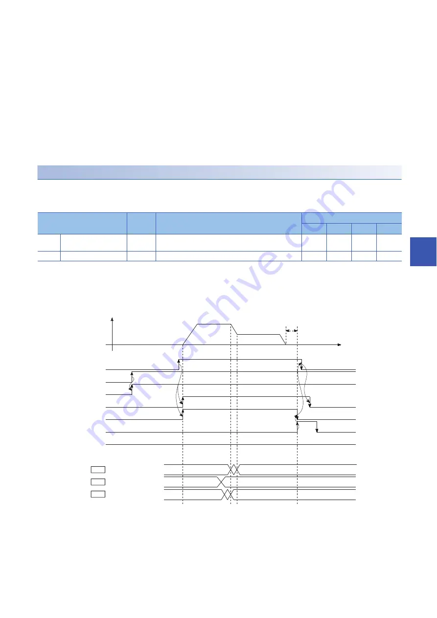
• The following shows the time chart of the speed change.
• Add the following program to the control program, and write it to the CPU module.
Setting item
Setting
value
Setting detail
Buffer memory address
Axis 1
Axis 2
Axis 3
Axis 4
[Cd.14]
New speed value
2000
Set the new speed.
1514
1515
1614
1615
1714
1715
1814
1815
[Cd.15]
Speed change request
1
Set 1: Change the speed.
1516
1616
1716
1816
1
0
0
1
0
2000
0
V
t
Md.40
Cd.14
Cd.15
[Y10]
[Y0]
[X0]
[X10]
[XC]
[X14]
[X8]
In speed change processing
flag
New speed value
Speed change request
Positioning start signal
PLC READY signal
RD75 READY signal
Start complete signal
BUSY signal
Positioning complete
signal
Error detection signal
Dwell time
Содержание MELSEC iQ-R RD75P4
Страница 1: ...MELSEC iQ R Positioning Module User s Manual Application RD75P2 RD75P4 RD75D2 RD75D4 ...
Страница 2: ......
Страница 13: ...11 MEMO ...
Страница 19: ...17 CONTENTS INDEX 588 REVISIONS 592 WARRANTY 593 TRADEMARKS 594 ...
Страница 498: ...496 13 PROGRAMMING 13 2 List of Labels Used ...
Страница 503: ...13 PROGRAMMING 13 4 Program Example 501 13 ...
Страница 511: ...13 PROGRAMMING 13 4 Program Example 509 13 Torque change program Step operation program Skip program ...
Страница 512: ...510 13 PROGRAMMING 13 4 Program Example Teaching program Continuous operation interrupt program ...
Страница 513: ...13 PROGRAMMING 13 4 Program Example 511 13 Target position change program Absolute position restoration program ...
Страница 514: ...512 13 PROGRAMMING 13 4 Program Example Restart program Parameter data initialization program ...
Страница 515: ...13 PROGRAMMING 13 4 Program Example 513 13 Flash ROM write program Error reset program ...
Страница 516: ...514 13 PROGRAMMING 13 4 Program Example Stop program ...
Страница 565: ...APPENDICES Appendix 4 Operation Examples of When the Remote Head Module Is Mounted 563 A ...
Страница 568: ...566 APPENDICES Appendix 4 Operation Examples of When the Remote Head Module Is Mounted Common program ...
Страница 584: ...582 APPENDICES Appendix 4 Operation Examples of When the Remote Head Module Is Mounted Restart program ...
Страница 587: ...APPENDICES Appendix 4 Operation Examples of When the Remote Head Module Is Mounted 585 A Stop program ...
Страница 597: ......


