background image

Manual: R1300-X-00-X_EN        Release: 1.04                  © Elotech GmbH                            Page 1/20 


R 1300 


Multifunctional Controller


DIN-Format: 96 x 96 mm 


Installation depth: 122 mm 


Description and Operating Manual 


ELOTECH Industrieelektronik GmbH 
Verbindungsstrasse 27 

– 40723 HILDEN 

FON +49 2103 / 255 97 0     

FAX  +49 2103 / 255 97 29 

www.elotech.de                        Email: [email protected] 

Содержание R 1300

Страница 1: ...1300 Multifunctional Controller DIN Format 96 x 96 mm Installation depth 122 mm Description and Operating Manual ELOTECH Industrieelektronik GmbH Verbindungsstrasse 27 D 40723 HILDEN FON 49 2103 255 97 0 FAX 49 2103 255 97 29 www elotech de Email info elotech de ...

Страница 2: ...rdware and software described Nevertheless we are unable to preclude the possibility of deviations so that we are unable to assume warranty for full compliance The information given in the publication is however reviewed regularly Necessary amendments are incorporated in the following editions We would be pleased to receive any improvement proposals which you may have This document may not be pass...

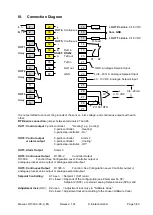
Страница 3: ... e g Cooling 3 point controller Heating 3 point step controller On OUT2 Control output 2 point controller Alarm 2 or alarm output 3 point controller Cooling 3 point step controller Off OUT3 Alarm Output Alarm 3 OUT4 Continuous Output R1300 2 Controller Output R1300 3 Function See Configuration Level Controller output or analogue process value output or analogue setpoint output OUT5 Continuous Outp...

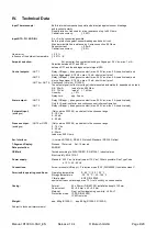
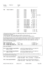
Страница 4: ...f 1 k Ohm Linearity 1 5 Delay time app 2 secs Alarm output OUT 2 Relay UR appr changeover contact max 250 Vac max 3 A resistive load Only for 2 point controller and continuous controller configuration OUT 3 Relay UR appr changeover contact max 250 Vac max 3 A resistive load Setpoint input Only version R1300 3 equivalent to the choosen range analogue 0 10 V dc 0 20 mA 4 20 mA Process output OUT4 or...

Страница 5: ...osen parameter e g setpoint to higher or lower values Short operation single step adjustment Longer operation quick scanning When the parameter adjustments have been altered but not entered The display will flash bright dark E Confirmation and storage of the pre selected values The display will shortly be switched dark as a control of this function P Sets the parameter back to the originally store...

Страница 6: ...n in succession be displayed by pressing the P key and adjusted by pressing the keys Parameter level Within the parameter level the values are adjusted to suit each individual process This level is reached by simultaneously pressing the P and E keys Configuration level In the configuration level the controller type input type sensor range alarm behaviour and the output type can be pre selected Thi...

Страница 7: ...Out4 Configuration Output 4 OFF Output OUT4 not active Only version R1300 2 and version R1300 3 if ConF 2Ph heating ConF 2Pc cooling ConF 2Pnc cooling if ConF 3P heating ConF 3Pnc heating Co h0 Control output 0 20mA 0 10V Co h4 Control output 4 20mA 2 10V if ConF 3P cooling ConF 3Pnc cooling Co c0 Control output 0 20mA 0 10V Co c4 Control output 4 20mA 2 10V Only version R1300 3 Pr 0 Process value...

Страница 8: ... following parameters are only valid for standard signal inputs 0 20mA 4 20mA 0 10Vdc The difference between the bottom end of the display range and the top end must amount to a minimum of 100 units and a maximum of 2000 units By adjustment of one of the above parameters the other in this case will automatically follow rA SP decimal points 0 1 2 ex works 1 rA Hi display range top end rA Lo 9999 ex...

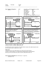
Страница 9: ...lected value is effective below and above controller is first switched on It is only then de the setpoint activated when the process value has been within and left the o k zone Switching behaviour Configuration Switching behaviour Configuration on off on off 3 off on off 7 on off on 6 setpoint process setpoint process on Relay activated or bistable voltage output high off Relay not active or bista...

Страница 10: ...old duration time At the end of this period the process value rises to the valid setpoint This results in a slower more regular heating period For this purpose the bistable voltage output must be chosen that actuates SSR relays If the softstart is active the controllers autotune function can t operated Er OP If a setpoint ramp has been programmed the softstart has priority and the ramp will only b...

Страница 11: ...been rectified the controller returns to automatic operation and calculates the required output ratio An additional signal can be issued in the event of sensor break if the alarm contacts are programmed accordingly Setting MAn The controller now operates only as an actuator Within the operation level an output ratio can be entered instead of the setpoint An H is then displayed as the first digit i...

Страница 12: ...adjustment cannot be changed if the external contact K2 is closed The following parameters are only valid if the unit is equipped with a serial interface Only version R 1300 2 Adr Unit adress 1 255 ex works 1 The computer adresses the unit at this adress Each unit has ist own adress It is possible to adress 32 units For Data format 7E1 7 data even 1 stopbit 7o1 7 data odd 1 stopbit 7E2 7 data even...

Страница 13: ... permissible limited ratio Warning The output ratio limitation does not work during autotune 1 P OUT 1 prop band P OFF 0 1 100 0 ex works 3 0 OUT 4 if Xp OFF the next parameter to follow is 1 Sd control sensivity OUT 1 1 d OUT 1 rate D OFF 1 200 secs ex works 30 OUT 4 1 J OUT 1 reset I OFF 1 1000 secs ex works 150 OUT 4 Normally the controller works using PD I control action This means controlling...

Страница 14: ...int for cooling output by the displayed value It can be help to reduce the switching frequency between the heating and cooling outputs if this is to high Simultaneously activation of heat and cool outputs is not possible 2 P OUT2 OUT5 cooling OFF 0 1 100 0 ex works 6 0 prop band P if Xp OFF the next parameter to follow is 2 Sd control sensitivity OUT 2 2 d OUT2 OUT5 coolingOFF 1 200 secs ex works ...

Страница 15: ...reset time I 0 5 80 0 min ex works 3 0 Sd control sensivity OFF 0 1 80 0 units ex works OFF OFF 0 01 8 00 units 1 OFF 0 001 0 800 units 2 Sh dead band OFF 0 1 80 0 units ex works OFF OFF 0 01 8 00 units 1 OFF 0 001 0 800 units 2 on off Sh on off Sd SETPOINT PROCESS 3 point step controllers use PI control action in combination with motor actuators It is important that SH should be several times lar...

Страница 16: ...The tuning algorithm can be activated at any time by selecting the OPT on and pressing the E key During self tuning Opt is shown in the display alternating with the setpoint value Using the heat cool controller the temperature drop will be accelerated by switching on the cooling for a short duration After having calculated the correct feedback parameters the controller will lead the process value ...

Страница 17: ...splay Please note that the value of the second setpoint cannot be changed in the oprating level In order to change the value the parameter SP2 has to be selected SP rising ramp OFF 0 1 100 0 units min ex works OFF OFF 0 01 10 00 units min 1 OFF 0 001 1 000 units min 2 SP falling ramp OFF 0 1 100 0 units min ex works OFF OFF 0 01 10 00 units min 1 OFF 0 001 1 000 units min 2 A programmed ramp is al...

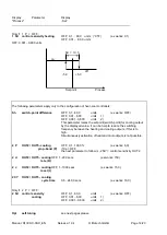
Страница 18: ... level AL 2 Alarm 2 Out2 signal contact setpoint dependent OFF 999 1000 units ex works OFF 99 9 100 0 1 OFF 9 99 10 00 2 limit comparator setpoint dependent OFF 1 1000 units ex works OFF 0 1 100 0 1 OFF 0 01 10 00 2 limit contact process value dependent OFF range bottom range top The following parameter is only shown if the controller is configurated as a 3 point step controller Hand manual mode O...

Страница 19: ...th two decimal points 4 SP Lo lower setpoint limitation SP Hi upper setpoint limitation XI Installation Instructions Make certain that the devices described here are used only for the intended purpose They are intended for installation in control panels The controller must be installed so that it is protected against impermissible humidity and severe contamination In addition make sure that the pe...

Страница 20: ...Manual R1300 X 00 X_EN Release 1 04 Elotech GmbH Page 20 20 ...

Отзывы: