Manual: R1300-X-00-X_EN Release: 1.04 © Elotech GmbH Page 3/20
III.
Connection Diagram
L / -
1
29
+
15
+ OUT 2:
bistable, 0/18 VDC
OUT 4,
Continuous
N / +
2
30
-
16
Com. GND
3
31
+
17
+ OUT 1:
bistable, 0/18 VDC
OUT 5,
Continuous
4
32
-
18
OUT 1
5
33
B
RxD in
19
Relay
RS485
RS232
6
34
A
TxD out
20
7
35
TxD in
21
8
36
RxD out
22
GND, Analogue Setpoint Input
OUT 2
9
37
GND
23
+
0/4...20 mA, Analogue Setpoint Input
Relay
10
24
+
0...10 VDC, Analogue Setpoint Input
11
25
+
12
26
+
+
OUT 3
13
27
-
-
Relay
14
28
Z1
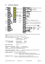
It is not permitted to connect the grounds of the sensor-, bist. voltage- and continuous-outputs with each
other.
RTD 2-wire connection:
jumper between terminals 27 and 26.
OUT1: Control output
2-point-controller:
"Heating" e.g „Cooling“
3-point-controller:
„Heating“
3-point-step-controller:
„On“
OUT2: Control output
2-point-controller:
Alarm 2
or alarm output
3-point-controller:
„Cooling“
3-point-step-controller:
„Off“
OUT3: Alarm Output
Alarm 3
OUT4: Continuous Output
R1300-2:
Controller Output
R1300-3:
Function: See Configuration Level. Controller output or
analogue process value output or analogue setpoint output
OUT5: Continuous Output
R1300-3:
Function: See Configuration Level. Controller output or
analogue process value output or analogue setpoint output
Setpoint Controlling:
K1: open = Setpoint 1 (SP1) valid
K1: closed = Depends of the configuration (see Parameter Co.SP):
Setpoint 2 (SP2) or external, analog Setpoint value (SPA) valid
Adjustment lock
(LOC)
:
K2: open = Adjustment lock only via "Software Code"
K2: closed. = Adjustment locked (according to the chosen Software Code)
R Load
R Load
K1
K2
Pt 100 / RTD
TC
0...10 VDC
0/4...20mA


