Wiring
Control circuit specifications
FR-D700 SC EC
3 - 25
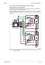
Safety stop when operating multiple frequency inverters in parallel
Wiring of frequency inverters FR-D700 SC
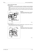
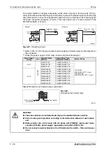
The safety stop function can be applied when using multiple FR-D740 SC and FR-D720S SC in-
verters. Connect as shown in the diagram below.
Details of the safety stop function are written on the "FR-D700 SC EC – Safety stop function in-
struction manual (BCN-A211508-005)". You can download the manual from the Mitsubishi
homepage.
I002184E
Fig. 3-16:
Connection of multiple frequency inverters to a safety relay module when using the
safety stop function
+24V
K1
X0 X1
COM0 COM1
24G
XS0 XS1
Z10
Z00 Z20
Z11
Z01 Z21
K2
S2
S1
FR-D700 SC
CPU
U V
W
IM
G
G
+24 V
SC
S2
S1
FR-D700 SC
CPU
R/L1
T/L3
U V
W
IM
S/L2
G
G
+24 V
SC
R/L1
T/L3
S/L2
RUN (SAFE2)
SE
SE
RUN
(SAFE2)
Emergency
stop button
START
Internal
safety
circuit
Gate
driver
Gate
driver
IGBTs
Gate
driver
Gate
driver
IGBTs
M
3~
24V DC
Safety relay module
MITSUBISHI MELSEC
QS90SR2SN-Q
Содержание FR-D720S SC EC
Страница 2: ......
Страница 4: ......
Страница 24: ...Description of the case Product checking and part identification 1 4 ...
Страница 108: ...Operation panel Operation 4 20 ...
Страница 436: ...Setting for the parameter unit and operation panel Parameter 6 286 ...
Страница 484: ...Measurements on the main circuit Maintenance and inspection 8 14 ...
Страница 504: ...Specification change Appendix A 20 ...
Страница 505: ......
Страница 506: ......
Страница 510: ...Index Appendix A 24 ...
Страница 511: ......


