


Wiring
Control circuit specifications
FR-D700 SC EC
3 - 23
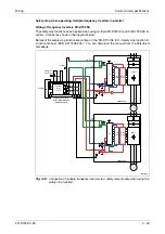
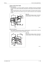
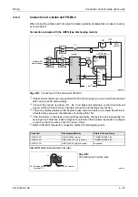
Wiring connection diagram
To prevent restart at fault occurrence, connect terminals RUN (SAFE2 signal) and SE to ter-
minals XS0 and XS1, because polarity of XS0 is positive, and polarity of XS1 is negative.
To prevent restart at fault occurrence, connect terminals RUN (SAFE2 signal) and SE to ter-
minals XS0 and XS1, which are the feedback input terminals of the safety relay module.
By setting Pr.190 to "81" (SAFE2 signal), terminal RUN is turned OFF at fault occurrence.
After the power-up, to reset the safety stop mode, press the START switch, and also press the
STF switch, then start the motor rotation. In the above wiring example, the motor rotation will not
occur in the event of reset of ‘safe-condition’ until STF is pressed.
I002074E
Fig. 3-15:
Connecting the Safety relay module QS90SR2SN-Q of Mitsubishi
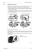
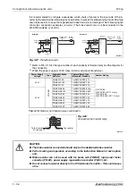
NOTE
Changing the terminal assignment using Pr. 190, Pr. 192 or Pr. 197 may affect the other
functions. Make setting after confirming the function of each terminal.
b
CAUTION:
To prevent restart in case of recovering from input power loss of drive, 3-wired
connection for STF/STOP control is recommended. In case of 2-wire connection and
using latching type switch to short between STF and PC for starting, ensure the
compliance with safety requirement for the restarting when the drive recover from
input power loss.
+24V
K1
X0
X1
COM0
COM1
24G
XS0 XS1
Z10
Z00
Z20
Z11
Z01
Z21
K2
R/L1
U V W
S/L2 T/L3
24V DC
Pr. 178 = 60 (initial value)
Pr. 179 = 25
Pr. 190 = 81
Pr. 197 = 80 (initial value)
STOP
Internal safety
circuit
Emergency stop
button
Output shutoff
circuit
I/O control
START/RESET
SO (SAFE)
Monitor
RUN (SAFE2)
SE
STF
STR (STOP)
S1
S2
SC
PC
Inverter
M
3~
Output signals differ by the setting of Pr. 190, Pr. 192
and Pr. 197.
Input signals differ by the setting of Pr. 178 to Pr. 182.
Safety relay module
MITSUBISHI MELSEC
QS90SR2SN-Q
Содержание FR-D720S SC EC
Страница 2: ......
Страница 4: ......
Страница 24: ...Description of the case Product checking and part identification 1 4 ...
Страница 108: ...Operation panel Operation 4 20 ...
Страница 436: ...Setting for the parameter unit and operation panel Parameter 6 286 ...
Страница 484: ...Measurements on the main circuit Maintenance and inspection 8 14 ...
Страница 504: ...Specification change Appendix A 20 ...
Страница 505: ......
Страница 506: ......
Страница 510: ...Index Appendix A 24 ...
Страница 511: ......