Control circuit specifications
Wiring
3 - 14
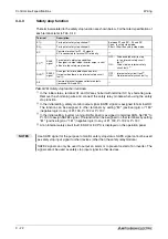
Terminal
Name
Description
Rated
Specifications
Refer to
Page
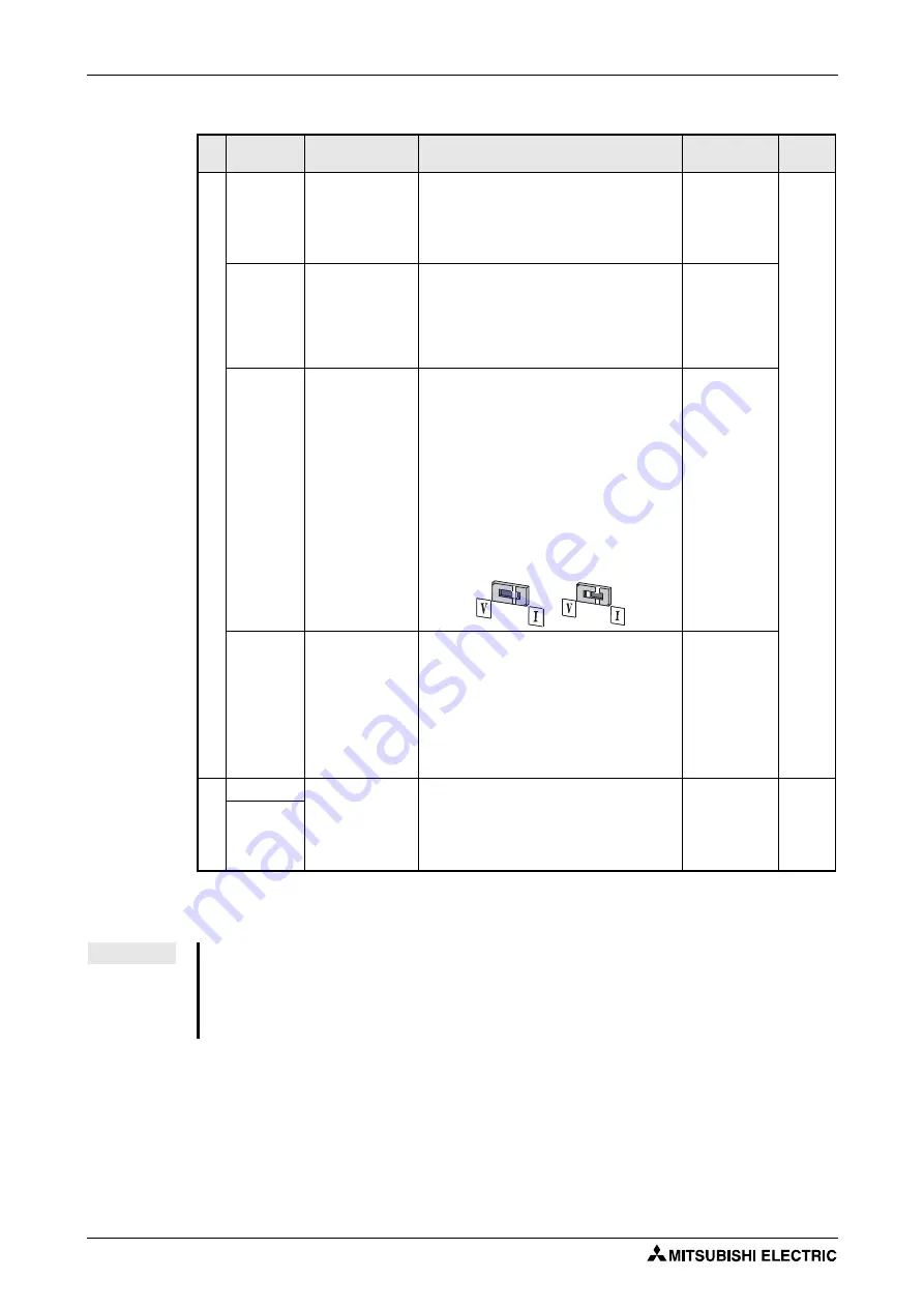
F
requency setting
10
(Output
voltage
5V DC)
Frequency setting
power supply
Used as power supply when connecting poten-
tiometer for frequency setting (speed setting)
from outside of the inverter.
Rated output voltage: 5V DC
Recommended potentiometer: 1k
Ω
, 2W linear,
multi turn potentiometer
5.0V DC ± 0,2V,
Permissible
load current
10mA
2
Frequency setting
(voltage)
Inputting 0 to 5V DC (or 0 to 10V) provides the
maximum output frequency at 5V (10V) and
makes input and output proportional. Use
Pr. 73 to switch from among input 0 to 5V DC
(initial setting), 0 to 10V DC.
Input resist-
ance:
10k
Ω
± 1k
Ω
Maximum
permissible
voltage:
20V DC
4
Frequency setting
(current)
Inputting 4 to 20mA DC (or 0 to 5V, 0 to 10V)
provides the maximum output frequency at
20mA and makes input and output propor-
tional. This input signal is valid only when the
AU signal is on (terminal 2 input is invalid).
To use terminal 4 (initial setting is current
input), set "4" in any of Pr.178 to Pr.182 to
assign the function, and turn ON AU signal.
Use Pr. 267 to switch from among input 4 to
20mA (initial setting), 0 to 5V DC and 0 to
10V DC. Set the voltage/current input switch in
the "V" position to select voltage input (0 to 5V/
0 to 10V).
Current input:
Input resist-
ance:
249
Ω
± 5
Ω
Maximum
permissible
current: 30mA
Voltage input:
Input resist-
ance:
10k
Ω
± 1k
Ω
Maximum
permissible
voltage:
20V DC
5
Frequency setting
common
Terminal 5 provides the common reference
potential (0V) for all analog set point values
and for the analog output signals AM (voltage).
The terminal is isolated from the digital circuit’s
reference potential (SD). This terminal should
not be grounded. If local regulations require
grounding of the reference potential note that
this can propagate any noise in the ground
potential to the control electronics, thus
increasing sensitivity to interference.
—
PTC ther
mistor
10
PTC thermistor
input
For connecting PTC thermistor output (thermal
motor protection).
When PTC thermistor protection is valid
(Pr. 561
≠
9999) terminal 2 is not available for
frequency setting.
PTC thermis-
tor resistance:
500
Ω
–30k
Ω
(Set by Pr. 561)
2
Tab. 3-9:
Input signals (2)
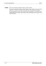
NOTE
Set Pr. 267 and a voltage/current input switch correctly, then input analog signals in accord-
ance with the settings.
Applying a voltage with voltage/current input switch in "I" position (current input is selected)
or a current with switch in"V" position (voltage input is selected) could cause component
damage of the inverter or analog circuit of output devices. Refer to section 6.15 for details.
Voltage input
Current input
(initial status)
Содержание FR-D720S SC EC
Страница 2: ......
Страница 4: ......
Страница 24: ...Description of the case Product checking and part identification 1 4 ...
Страница 108: ...Operation panel Operation 4 20 ...
Страница 436: ...Setting for the parameter unit and operation panel Parameter 6 286 ...
Страница 484: ...Measurements on the main circuit Maintenance and inspection 8 14 ...
Страница 504: ...Specification change Appendix A 20 ...
Страница 505: ......
Страница 506: ......
Страница 510: ...Index Appendix A 24 ...
Страница 511: ......


