


(T) Multi-Function Input Terminal Parameters
419
5
GROUP
T
5.12.10
External fault input signal
The inverter output can be shut off by inputting the External fault input (X32) signal when an external fault occurs. To assign
the X32 signal, set "32" in any of
Pr.178 to Pr.189 (Input terminal function selection).
Details of the operation
• When the External fault input (X32) signal turns OFF during operation, the inverter activates the protective function with the
indication "E.EF" displayed to shut off the output.
• When the X32 signal turns OFF during a stop, the protective function is not activated ("E.EF" is not displayed).
• When the inverter operation is started with the X32 signal OFF, the inverter activates the protective function immediately to
shut off the output.
NOTE
• When the X32 signal turns OFF during zero speed control or pre-excitation while the start signal is OFF, the inverter output is
shut off.
• When the inverter operation is started with the X32 signal OFF, the inverter may output the AC voltage for an extremely brief
moment.
5.12.11
Selecting operation condition of the second
function selection signal (RT) and the third
function selection signal (X9)
• Turning ON the Second function selection (RT) signal enables the second functions.
• Turning ON the Third function selection (X9) enables the third functions. For the X9 signal, set "9" in
Pr.178 to Pr.189
(Input terminal function selection)
to assign the function.
• The following table lists application examples of the second (third) functions.
- Switching between regular use and emergency use
- Switching between heavy load and light load
- Change the acceleration/deceleration time by break point acceleration/deceleration
- Switching characteristics of main motor and sub motor
The second function can be selected using the RT signal, and the third function can be selected using the X9 signal.
The condition to activate the second or third function can be also set.
Pr.
Name
Initial value
Setting range
Description
155
T730
RT signal function validity
condition selection
0
0
The second function is immediately enabled when
the RT signal is turned ON, and the third function
is immediately enabled when the X9 signal is
turned ON.
10
The function cannot be changed to the second or
third function during acceleration/deceleration.
When the signal is turned ON during acceleration/
deceleration, the function is changed after the
acceleration/deceleration is finished.
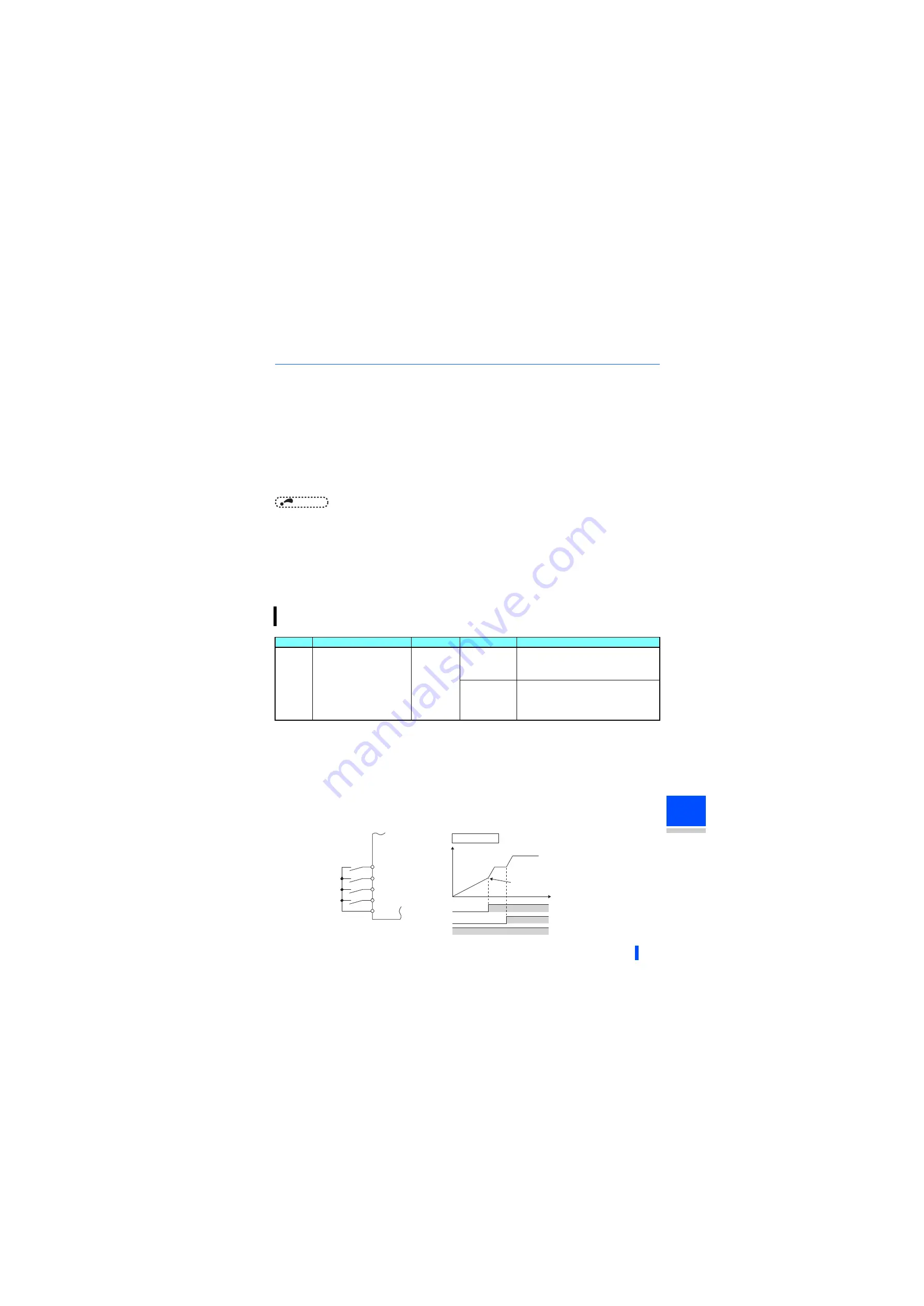
Connection diagram for second
function selection
Example of second
acceleration/deceleration time
STF/STR
SD
Inverter
Start
Second function selection
RT
High speed
RH
Middle speed
RM
(initial value)
RT
Output frequency
Setting value "0"
RH
RM
Acceleration
time is applied
Time
Содержание 800 Series
Страница 11: ...MEMO 10 ...
Страница 17: ...MEMO 16 ...
Страница 95: ...MEMO 94 ...
Страница 671: ...MEMO 670 ...
Страница 681: ...MEMO 680 ...