


(F) Setting of acceleration/deceleration time and acceleration/deceleration pattern
286
• When the shortest acceleration/deceleration is selected under V/F control and Advanced magnetic flux vector control, the
stall prevention operation level during acceleration/deceleration becomes 150% (adjustable using
Pr.61 to Pr.63
). The
setting of
Pr.22 Stall prevention operation level
and stall level by analog input are used only during a constant speed
operation.
Under Real sensorless vector control and vector control, the torque limit level (
Pr.22
, etc.) is applied during acceleration/
deceleration. The adjustments by
Pr.61
to
Pr.63
are disabled.
• It is inappropriate to use for the following applications.
-Machines with large inertia (10 times or more), such as a fan. Since stall prevention operation will be activated for a long
time, this type of machine may trip due to motor overloading, etc.
-When the inverter is always operated at a specified acceleration/deceleration time.
NOTE
• Even if automatic acceleration/deceleration has been selected, inputting the JOG signal (JOG operation), RT signal (second
function selection) or X9 signal (third function selection) during an inverter stop will switch to the normal operation and give
priority to JOG
operation, second function selection or third function selection. Note that during operation, an input of JOG and RT signal
does not have any influence even when the automatic acceleration/deceleration is enabled.
• Since the shortest acceleration/deceleration is made with the stall prevention operation being activated, the acceleration/
deceleration speed always varies according to the load conditions.
• By setting
Pr.7
and
Pr.8
appropriately, it is possible to accelerate/decelerate with a shorter time than when selecting the
shortest acceleration/deceleration.
Optimum acceleration/deceleration (Pr.292 = "3", Pr.293)
• The inverter operates at the most efficient level within the rated range that can be used continuously with reasonable
inverter capacity. Using self-learning, the average current during acceleration/deceleration is automatically set so as to become the
rated current. This is ideal for applications operated with a predetermined pattern and minimal load fluctuations, such as by
an automatically operated conveyor.
• When the optimum acceleration/deceleration is selected, at first, the operation is performed with the values set in
Pr.0
Torque boost
,
Pr.7 Acceleration time
, and
Pr.8 Deceleration time
. After the first operation is completed, average and
peak currents are calculated based on the motor current during acceleration/deceleration, and the obtained values are
compared with the reference current (initially set to the inverter rated current) to adjust the
Pr.0
,
Pr.7
, and
Pr.8
settings to
their optimal values. The operation is the performed with the updated
Pr.0
,
Pr.7
, and
Pr.8
values onwards, and those
parameters settings are adjusted each time. Under Advanced magnetic flux vector control, Real sensorless vector control
and vector control, however, the
Pr.0
setting is not changed.
• When a Regenerative overvoltage trip during deceleration or stop (E.OV3) occurs during deceleration, the setting of
Pr.8
is
multiplied by 1.4.
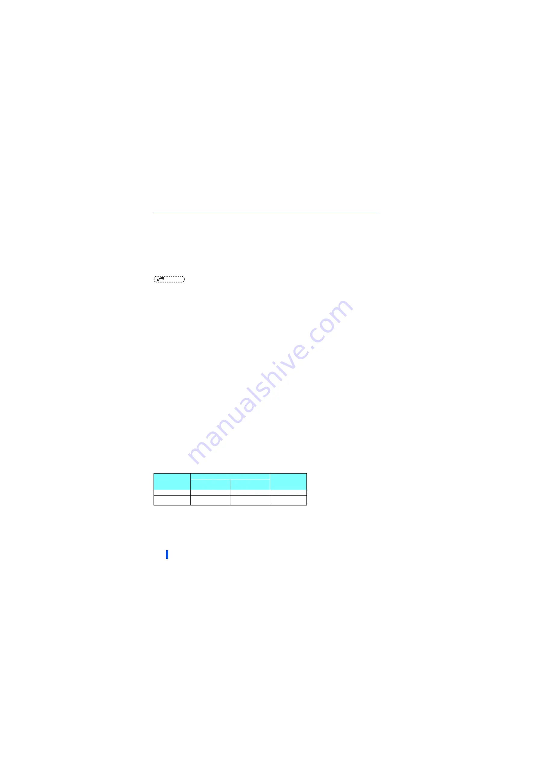
• Parameter storage
The optimum values of
Pr.0, Pr.7 and Pr.8
are written to both the parameter RAM and EEPROM only three times of
acceleration (deceleration) after the optimum acceleration/deceleration has been selected or after the power is switched
ON or the inverter is reset. At or after the fourth attempt, they are not stored into EEPROM. Hence, after power-ON or
inverter reset, the values changed at the third time are valid. However, the optimum values are calculated even for the
fourth time and later, and
Pr.0, Pr.7, and Pr.8
are set to the RAM; therefore, these can be stored to the EEPROM by
reading and writing the settings with the operation panel.
• Either acceleration or deceleration can be made in the optimum acceleration/deceleration using
Pr.293 Acceleration/
deceleration separate selection
. When the setting value is "0" (initial value), both acceleration and deceleration are made
in the optimum acceleration/deceleration.
• It is inappropriate for machines which change in load and operation conditions.
Optimum values are saved for the next operation. If the operating condition changes before the next operation, a fault such
as overcurrent trip or a lack of acceleration/deceleration may occur.
Number of
optimum value
changes
Pr.0, Pr.7, Pr.8
Operating
condition
EEPROM value
RAM value
1 to 3 times
Updated
Updated
Updated
4 and more times
Unchanged from the
3rd value
Updated
Updated
Содержание 800 Series
Страница 11: ...MEMO 10 ...
Страница 17: ...MEMO 16 ...
Страница 95: ...MEMO 94 ...
Страница 671: ...MEMO 670 ...
Страница 681: ...MEMO 680 ...