


(A) Application parameters
486
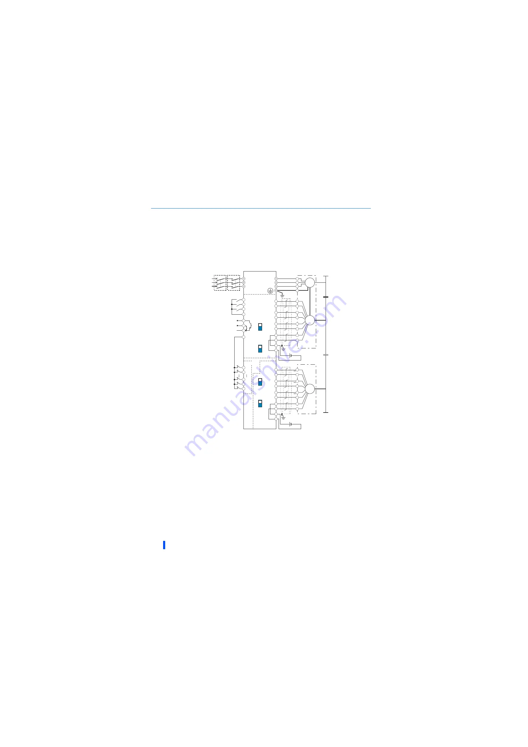
Machine end orientation connection diagram (Vector control)
• To perform machine end orientation control, the following settings are required.
- Install a plug-in option (FR-A8AP/FR-A8AL or FR-A8APR) and a control terminal option (FR-A8TP) to the inverter, a
motor end encoder to the control terminal option, and a machine end encoder to the plug-in option.
- Set
Pr.862 Encoder option selection
="1".
- Set
Pr.393 Orientation selection
="10 to 12". (Refer to
.)
- Set the gear ratio by setting
Pr.394 Number of machine side gear teeth
and
Pr.395 Number of motor side gear teeth
.
The pin number differs according to the encoder used.
Use
Pr.178 to Pr.182, Pr.185, or Pr.189 (Input terminal function selection)
to assign the function to a terminal. (Refer to
.)
Use
Pr.190 to Pr.192, or Pr.195 (Output terminal function selection)
to assign the function to a terminal. (Refer to
.)
Connect the encoder so that there is no looseness between the motor and motor shaft. Speed ratio must be 1:1.
Earth (ground) the shield of the encoder cable to the enclosure using a tool such as a P-clip. (Refer to
.)
For the differential line driver, set the terminating resistor selection switch to the ON position. (Refer to
.)
Note that the terminating resistor switch should be set to the OFF position (initial status) when sharing the same encoder with another unit (NC,
etc.) having a terminating resistor under the differential line driver setting.
For the complementary, set the switch to the OFF position.
For terminal compatibility between the FR-A8TP and the FR-JCBL/FR-V7CBL, refer to the Instruction Manual of the FR-A8TP.
A separate power supply of 5 V/12 V/15 V is necessary according to the encoder power specification. When the encoder output is the differential
line driver type, only 5 V can be input. Make the voltage of the external power supply same as the encoder output voltage, and connect the
external power supply between PG and SD. If using the 24V power supply of the FR-A8TP, 24V power can be supplied from terminal PG24.
When performing encoder feedback control and Vector control together, an encoder and power supply can be shared.
The encoder and the power supply can be shared under orientation control, encoder feedback control, or vector control.
When a stop position command is input from outside, a plug-in option FR-A8AX is required. Refer to
for the external stop position
command.
R/L1
S/L2
T/L3
DY
U
V
W
U
V
W
E
C
∗5
∗1
∗4
∗9
∗6
∗7
X0
X1
X14
X15
R
PA3
PAR3
PB3
PBR3
PZ3
PZR3
PG
PG
SD
SD
OFF
A
N
B
P
H
K
IM
∗6
OFF
STF
STR
SD
SD
X22
∗2
ORM
ORA
∗3
SE
∗3
FR-A8AX
FR-A8TP
FR-A8AP
(+)
(-)
A
∗5
∗1
∗4
A
PA1
PA2
PB1
PB2
PZ1
PZ2
PG
PG
SD
SD
B
B
Z
Z
+
-
(+)
(-)
MC
Machine end
encoder
(differential
line driver)
Machine end
encoder
(differential
line driver)
Machine end
encoder
(differential
line driver)
Three-phase
AC power
supply
MCCB
Forward rotation start
Reverse rotation start
Orientation command
Contact input common
Inverter
Differential
Terminating
resistor ON
Complementary
Differential
Terminating
resistor ON
Complementary
Power supply
∗8
Encoder
5 VDC power
supply
∗8
Encoder
Earth
(Ground)
Содержание 800 Series
Страница 11: ...MEMO 10 ...
Страница 17: ...MEMO 16 ...
Страница 95: ...MEMO 94 ...
Страница 671: ...MEMO 670 ...
Страница 681: ...MEMO 680 ...