Machine Protection
6-
47
K
K
K
K
Motor
Overload
Protection
You
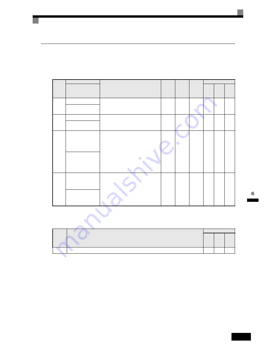
can protect the motor from overload using the Inverter's built-in electronic thermal overload relay.
n
Related
Parameters
* 1. Factory
settings depend on Inverter capacity. (The values shown are for a 200 V Class Inverter for 0.4 kW.)
* 2. The
settings range is 10% to 200% of the Inverter rated output current. (The values shown are for a 200 V Class Inverter for 0.4 kW.)
Multi-Function
Digital
Outputs
(H2-01
to
H2-03)
Param-
eter
Num-
ber
Name
Description
Setting
Range
Factory
Setting
Change
during
Opera-
tion
Control
Methods
V/f
V/f
with
PG
Open
Loop
Vec-
tor
LCD
Display
E2-01
Motor
rated current
Set
the motor rated current in amps.
This
set value becomes the base value for motor
protection
and torque limit. It is set automatically
when
using autotuning.
0.32
to
6.40
*2
1.90
A
*1
No
Q
Q
Q
Motor
Rated FLA
E4-01
Motor
2 rated current
Set
the motor rated current in Amps.
This
set value becomes the base value for motor
protection
and torque limit. It is set automatically
when
using autotuning.
0.32
to 6.40
*2
1.90
A
*1
No
A
A
A
Motor
Rated FLA
L1-01
Motor
protection selection
Set
to enable or disable the motor overload protec-
tion
function using the electronic thermal relay.
0:
Disabled
1:
General motor protection
2:
Inverter special motor protection
3:
Vector motor protection
With
applications where the power supply is often
turned
ON and OFF, there is a risk that the circuit
cannot
be protected even if this parameter has
been
set to 1, as the thermal value will be reset. If
multiple
motors are connected to one Inverter, set
this
parameter to 0, and install a thermal relay in
0
to 3
1
No
Q
Q
Q
MOL
Fault Select
L1-02
Motor
protection time con-
stant
Set
the electronic thermal detection time in min-
utes.
Normally,
there is no need to make this setting.
The
factory setting is resistance at 150% for 1 min.
If
the motor overload resistance is clear, set the
overload
resistance protection time during hot
start
to suit the motor.
0.1
to
5.0
(0.1
to
20.0)
1.0
min
(8.0
min)
No
A
A
A
MOL
Time Const
Set
Value
Function
Control
Methods
V/f
V/f
with
PG
Open
Loop
Vec-
tor
1F
Motor
overload (OL1, including OH3) pre-alarm (ON: 90% or more of the detection level)
Yes
Yes
Yes
Summary of Contents for SYSDRIVE 3G3RV
Page 1: ...USER S MANUAL SYSDRIVE 3G3RV High function General purpose Inverters Cat No I532 E1 1...
Page 36: ...1 22...
Page 106: ...3 14...
Page 126: ...4 20...
Page 216: ...5 90...
Page 388: ...7 26...


