


M451
May. 4, 2018
Page
877
of
1006
Rev.2.08
M4
51
S
E
RI
E
S
T
E
CH
NICA
L RE
F
E
R
E
NC
E
M
A
NU
A
L
10% of the bit time is not suitable for short bit times; it can be used for bit rates of up to 125 Kbit/s (bit
time = 8us) with a bus length of 40 m.
Configuring the CAN Protocol Controller
6.20.7.20
In most CAN implementations and also in the C_CAN, the bit timing configuration is programmed in
two register bytes. The sum of Prop_Seg and Phase_Seg1 (as TSEG1 (CAN_BTIME[11:8])) is
combined with Phase_Seg2 (as TSEG2 (CAN_BTIME[14:12])) in one byte, SJW (CAN_BTIME[7:6])
and BRP (CAN_BTIME[5:0]) are combined in the other byte.
In these bit timing registers, the four components TSEG1, TSEG2, SJW and BRP have to be
programmed to a numerical value that is one less than its functional value. Therefore, instead of
values in the range of [1..n], values in the range of [0..n-1] are programmed. That way, e.g. SJW
(functional range of [1..4]) is represented by only two bits.
Therefore the length of the bit time is (programmed values) [TSEG1 + TSEG2 + 3] t
q
or (functional
values) [Sy Pr Phas Phase_Seg2] t
q
.
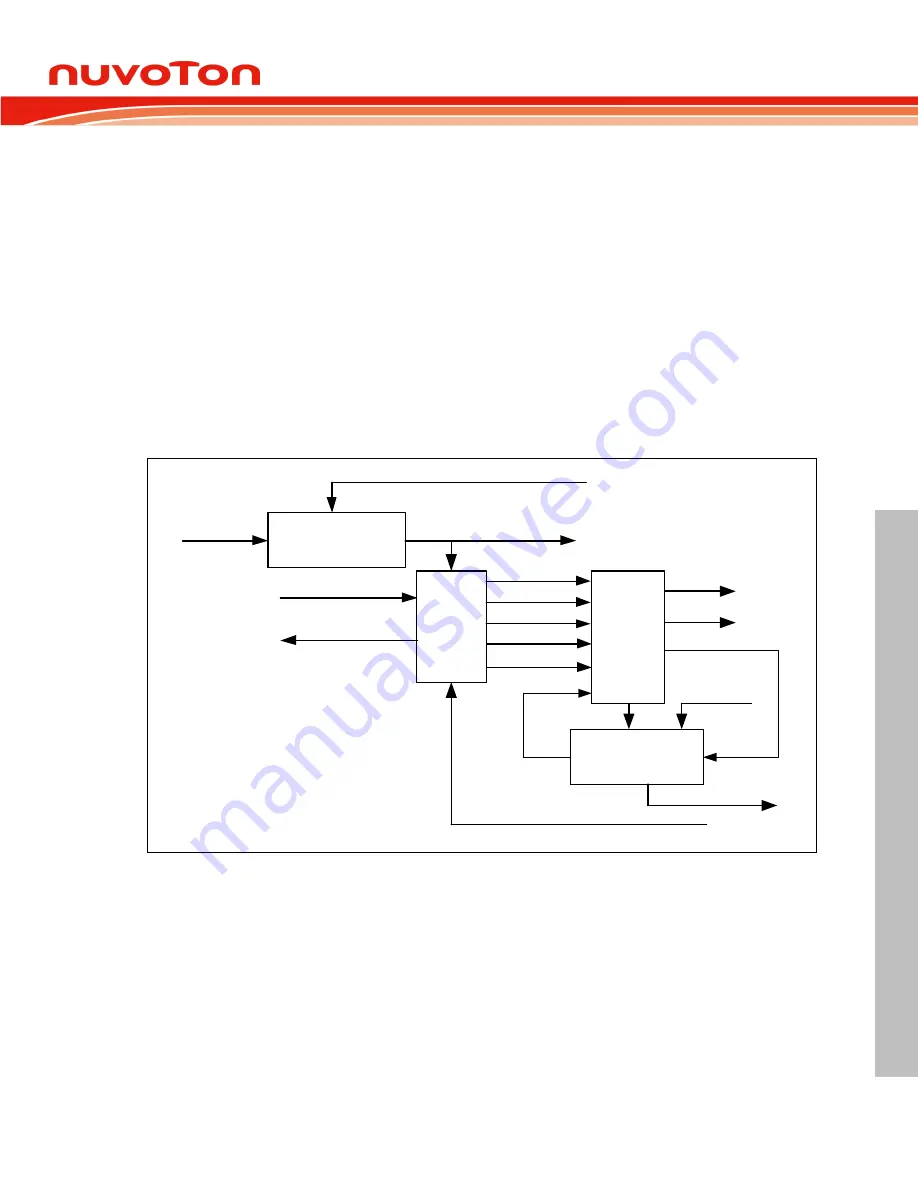
Baudrate_Prescaler
APB Clock
Configuration (BRP)
Bit
Timing
Logic
Received_Data
Transmit_Data
Sample_Point
Sample_Bit
Sync_Mode
Bit_to_send
Bus_Off
Bit
Stream
Processor
Control
Status
Shift-Register
Received_Data_Bit
Send_Message
Control
Next_Data_Bit
Received_Message
Configuration (TSEG1, TSEG2,SJW)
Scaled_Clock (
t
q
)
Figure 6.20-11
Structure of the CAN Core’s CAN Protocol Controller
The data in the bit timing registers is the configuration input of the CAN protocol controller. The Baud
Rate Prescaler (configured by BRP) defines the length of the time quantum, the basic time unit of the
bit time; the Bit Timing Logic (configured by TSEG1, TSEG2 and SJW) defines the number of time
quanta in the bit time.
The processing of the bit time, the calculation of the position of the Sample Point, and occasional
synchronizations are controlled by the BTL (Bit Timing Logic) state machine, which is evaluated once
each time quantum. The rest of the CAN protocol controller, the BSP (Bit Stream Processor) state
machine is evaluated once each bit time, at the Sample Point.
The Shift Register sends the
messages serially and parallelizes received messages. It’s loading and
shifting is controlled by the BSP.


