


M451
May. 4, 2018
Page
589
of
1006
Rev.2.08
M4
51
S
E
RI
E
S
T
E
CH
NICA
L RE
F
E
R
E
NC
E
M
A
NU
A
L
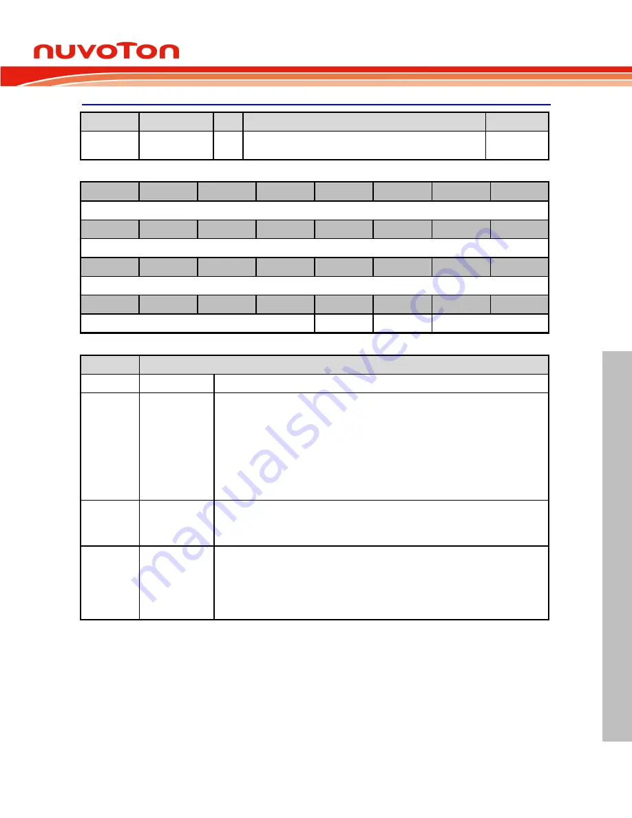
TAMPER Control Register (RTC_TAMPCTL)
Register
Offset
R/W
Description
Reset Value
RTC_TAMPC
TL
0x10C
R/W
TAMPER Pin Control Register
0x0000_0000
31
30
29
28
27
26
25
24
Reserved
23
22
21
20
19
18
17
16
Reserved
15
14
13
12
11
10
9
8
Reserved
7
6
5
4
3
2
1
0
Reserved
CTLSEL
DOUT
OPMODE
Bits
Description
[31:4]
Reserved
Reserved.
[3]
CTLSEL
IO Pin State Backup Selection
When tamper function is disabled, TAMPER pin can be used as GPIO function. User can
program CTLSEL bit to decide PF.2 I/O function is controlled by system power domain
GPIO module or V
BAT
power domain RTC_TAMPCTL control register.
0 =TAMPER (PF.2) I/O function is controlled by GPIO module. It becomes floating state
when system power is turned off.
1 =TAMPER (PF.2) I/O function is controlled by V
BAT
power domain. PF.2 function and I/O
status are controlled by OPMODE[1:0] and DOUT after CTLSEL it set to 1. I/O pin state
keeps previous state after system power is turned off.
[2]
DOUT
IO Output Data
0 = TAMPER (PF.2) output low.
1 = TAMPER (PF.2) output high.
[1:0]
OPMODE
IO Operation Mode
00 = TAMPER (PF.2) is input only mode, without pull-up resistor.
01 = TAMPER (PF.2) is output push pull mode.
10 = TAMPER (PF.2) is open drain mode.
11 = TAMPER (PF.2) is input only mode with internal pull up.


