A - 4
(2) Wiring
CAUTION
Wire the equipment correctly and securely. Otherwise, the servo motor may misoperate.
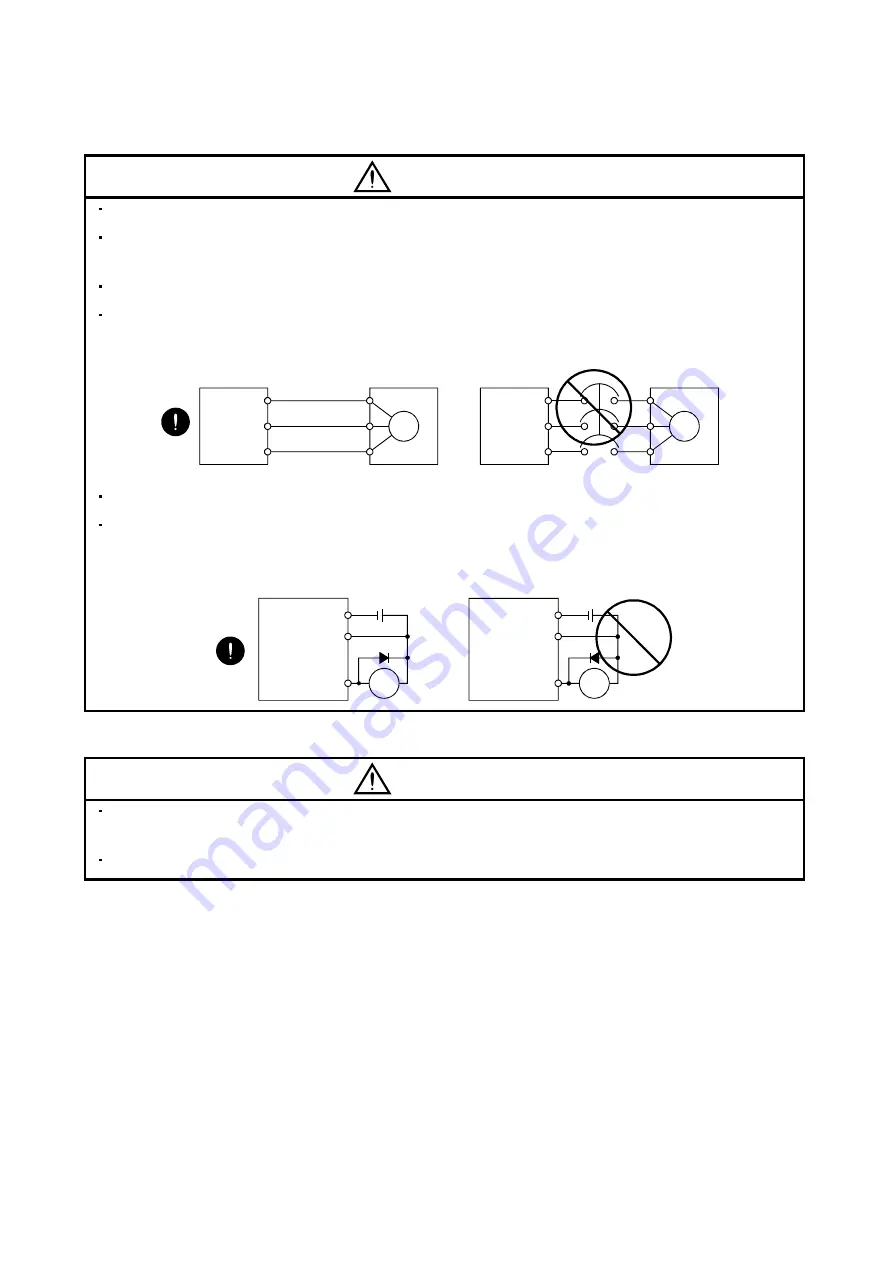
Do not install a power capacitor, surge absorber or radio noise filter (FR-BIF option) between the servo
motor and servo amplifier.
Connect the output terminals (U, V, W) correctly. Otherwise, the servo motor will operate improperly.
Connect the servo motor power terminal (U, V, W) to the servo motor power input terminal (U, V, W)
directly. Do not let a magnetic contactor, etc. intervene.
U
Servo Motor
M
V
W
U
V
W
U
M
V
W
U
V
W
Servo Amplifier
Servo Motor
Servo Amplifier
Do not connect AC power directly to the servo motor. Otherwise, a fault may occur.
The surge absorbing diode installed on the DC output signal relay of the servo amplifier must be wired in
the specified direction. Otherwise, the forced stop (EMG) and other protective circuits may not operate.
Servo
Amplifier
Control
output
signal
Servo
Amplifier
Control
output
signal
RA
DOCOM
DICOM
24VDC
RA
DOCOM
DICOM
24VDC
(3) Test run adjustment
CAUTION
Before operation, check the parameter settings. Improper settings may cause some machines to perform
unexpected operation.
The parameter settings must not be changed excessively. Operation will be insatiable.
Summary of Contents for MELSERVO MR-J3-xT
Page 22: ...8 MEMO ...
Page 156: ...4 46 4 SIGNALS AND WIRING MEMO ...
Page 276: ...7 26 7 MR Configurator MEMO ...
Page 324: ...10 16 10 SPECIAL ADJUSTMENT FUNCTIONS MEMO ...
Page 418: ...14 66 14 OPTIONS AND AUXILIARY EQUIPMENT MEMO ...


