14 - 39
14. OPTIONS AND AUXILIARY EQUIPMENT
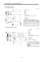
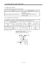
(1) Selection of dynamic brake
The dynamic brake is designed to bring the servo motor to a sudden stop when a power failure occurs
or the protective circuit is activated, and is built in the 7kW or less servo amplifier. Since it is not built
in the 11kW or more servo amplifier, purchase it separately if required. Assign the dynamic brake interlock
(DB) to any of CN6-14, CN6-15 and CN6-16 pins in parameter No.PD12 to PD14.
Servo amplifier
Dynamic brake
MR-J3-11KT DBU-11K
MR-J3-15KT DBU-15K
MR-J3-22KT DBU-22K
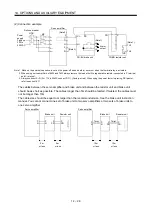
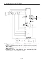
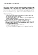
(2) Connection example
NFB
MC
L
11
L
21
U
V
W
U
V
W
M
13 U
14
V W
a
b
RA1
MC
SK
MC
ON
OFF
EMG
L
3
L
2
L
1
P
P
1
5
17
1
Plate
DB
DICOM
DOCOM
EMG
SD
RA1
24VDC
External dynamic brake
(Note 2)
(Note 3)
Power
supply
3-phase
200 to
230VAC
Operation-ready
(Note 1)
Servo amplifier
Servo motor
Note 1. Configure up the circuit to switch power off in the external sequence at servo alarm occurrence.
2. Terminals 13, 14 are normally open contact outputs. If the dynamic brake is seized, terminals 13, 14 will open.
Therefore, configure up an external sequence to prevent servo-on.
3. For the servo amplifiers from 11k to 22kW, be sure to connect P - P
1
. (Factory-wired)
When using the power factor DC reactor, refer to Section 14.11.
4. Assign the dynamic brake sequence (DB) in the parameters No.PD12 to PD14.
(Note 4)
CN6
Summary of Contents for MELSERVO MR-J3-xT
Page 22: ...8 MEMO ...
Page 156: ...4 46 4 SIGNALS AND WIRING MEMO ...
Page 276: ...7 26 7 MR Configurator MEMO ...
Page 324: ...10 16 10 SPECIAL ADJUSTMENT FUNCTIONS MEMO ...
Page 418: ...14 66 14 OPTIONS AND AUXILIARY EQUIPMENT MEMO ...

