6 - 6
6. PARAMETERS
6.1.8 Electronic gear
CAUTION
False setting will result in unexpected fast rotation, causing injury.
POINT
This parameter is made valid when power is switched off, then on after
setting, or when the controller reset has been performed.
The range of the electronic gear setting is
CMX
CDV
1
10
2000. If you set any
value outside this range, a parameter error (A37) occurs.
Setting "0" in parameter No.PA06 automatically sets the encoder resolution
pulse.
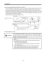
(1) Concept of electronic gear
Use the electronic gear (parameters No.PA06, PA07) to make adjustment so that the servo amplifier setting
matches the moving distance of the machine. Also, by changing the electronic gear value, the machine can
be moved at any multiplication ratio to the moving distance on the servo amplifier.
Parameters No. PA06
Parameters No. PA07
CMX
CDV
Electronic gear
Parameters No. PA06, PA07
Encoder feedback pulses
CMX
CDV
Deviation
counter
Motor
Encoder
M
ov
ing
dis
tanc
e
+
-
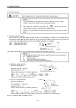
The following examples are used to explain how to calculate the electronic gear value:
POINT
The following specification symbols are needed for electronic gear calculation:
Pb : Ballscrew lead [mm]
n
: Reduction ratio
Pt
: Servo motor resolution [pulse/rev]
S : Travel per servo motor revolution [mm/rev]
(a) Ballscrew setting example
Machine specifications
Ballscrew lead: Pb 10 [mm]
Reduction ratio: n 1/2
Servo motor resolution: Pt 262144 [pulse/rev]
Servo motor 262144[pulse/rev]
n
NM
NL
Pb=10[mm]
n=NL/NM=1/2
CMX
CDV
S
p
t
5000
262144
625
32768
p
t
n 1000
p
b
262144
1/2 10 1000
Hence, set 32768 to CMX and 625 to CDV.
(b) Conveyor setting example
Machine specifications
Pulley diameter: r 160 [mm]
Reduction ratio: n 1/3
Servo motor resolution: Pt 262144 [pulse/rev]
Servo motor
262144[pulse/rev]
r=160[mm]
n
NM
NL
n=NL/NM=1/3
CMX
CDV
p
t
S
32768
20944
167551.61
262144
p
t
n r 1000
262144
1/3 160 1000
Reduce CMX and CDV to the setting range or less, and round off the first decimal place.
Hence, set 32768 to CMX and 20944 to CDV.
Summary of Contents for MELSERVO MR-J3-xT
Page 22: ...8 MEMO ...
Page 156: ...4 46 4 SIGNALS AND WIRING MEMO ...
Page 276: ...7 26 7 MR Configurator MEMO ...
Page 324: ...10 16 10 SPECIAL ADJUSTMENT FUNCTIONS MEMO ...
Page 418: ...14 66 14 OPTIONS AND AUXILIARY EQUIPMENT MEMO ...

