3 - 15
3. CC-LINK COMMUNICATION FUNCTIONS
Device No.
Signal name
Description
1 station
occupied
2 stations
occupied
Remarks
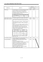
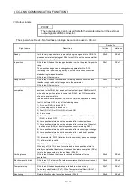
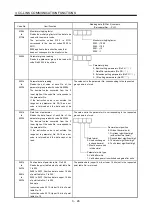
Position instruction demand
When RY(n+2)0 is turned ON, the point table No. or position
command data set to remote register RWwn+4/RWwn+5 is
set.
When it is set to the servo amplifier, the answer code
indicating normal or error is set to RWrn+2. At the same time,
RX(n+2)0 turns ON.
Refer to section 3.6.3 for details.
RY(n+2)0
Speed instruction demand
When RY(n+2)1 is turned ON, the point table No. or speed
command data set to remote register RWwn+6 is set.
When it is set to the servo amplifier, the answer code
indicating normal or error is set to RWrn+2. At the same time,
RX(n+2)1 turns ON.
Refer to section 3.6.3 for details.
RY(n+2)1
Internal torque limit selection
Turning RY(n+2)6 OFF makes the torque limit value of
parameter No. PA11 (forward rotation torque
limit) parameter No. PA12 (reverse rotation torque limit)
valid, and turning it ON makes that of parameter No. PC35
(internal torque limit). (Refer to section 4.6.3)
RY(n+2)6 1
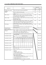
Proportion control
When RY(n+2)7 is turned ON, the speed amplifier is switched
from the proportional integral type to the proportional type.
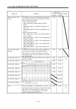
If the servo motor at a stop is rotated even one pulse by an
external factor, it develops torque in an attempt to
compensate for a position shift. When the shaft is locked
mechanically after Movement finish (RXnC) is turned OFF, for
example, turning Proportion control (RY(n+2)7) ON as soon
as Movement finish (RXnC) turns OFF allows control of
unnecessary torque developed in an attempt to compensate
for a position shift.
When the shaft is to be locked for an extended period of time,
turn Internal torque limit selection (RY(n+2)6) ON
simultaneously with Proportion control (RY(n+2)7) to make
the torque not more than the rated torque using Internal
torque limit (parameter No. PC35).
RY(n+2)7 1
2
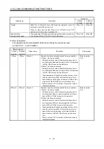
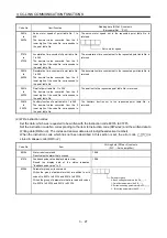
Gain changing
When RY(n+2)8 is turned ON, the load inertia moment ratio
and the corresponding gain values change to the values of
parameter No. PB29 to PB32. To change the gain using
RY(n+2)8, make the auto tuning invalid.
RY(n+2)8 1
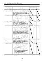
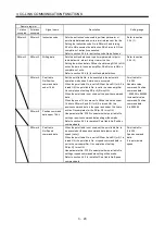
Position/speed specifying
system selection
Select how to give a position command/speed command.
(Refer to section 3.6.3.)
OFF: Remote input-based position/speed specifying system
Specifying the point table No. with Point table No.
selection (RYnA to RYnE) gives a position
command/speed command.
ON : Remote register-based position/speed specifying
system
Setting the instruction code to the remote register
(RWwn+4 to RWwn+6) gives a position
command/speed command.
Set the parameter No. PC30 (direct specification
selection) to "
2".
RY(n+2)A
Summary of Contents for MELSERVO MR-J3-xT
Page 22: ...8 MEMO ...
Page 156: ...4 46 4 SIGNALS AND WIRING MEMO ...
Page 276: ...7 26 7 MR Configurator MEMO ...
Page 324: ...10 16 10 SPECIAL ADJUSTMENT FUNCTIONS MEMO ...
Page 418: ...14 66 14 OPTIONS AND AUXILIARY EQUIPMENT MEMO ...

