14 - 58
14. OPTIONS AND AUXILIARY EQUIPMENT
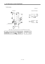
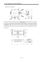
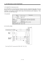
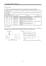
Outline drawing
Earth plate
Clamp section diagram
(Note)M4 screw
11
3
6
C
A
6
22
17.5
35
35
L or less
10
30
7
24
0 0.
2
Note. Screw hole for grounding. Connect it to the earth plate of the control box.
24
0
.3
0
[Unit: mm]
B
0
.3
2- 5 hole
installation hole
Type
A
B
C
Accessory fittings
Clamp fitting
L
AERSBAN-DSET
100
86
30
clamp A: 2pcs.
A
70
AERSBAN-ESET
70
56
clamp B: 1pc.
B
45
Summary of Contents for MELSERVO MR-J3-xT
Page 22: ...8 MEMO ...
Page 156: ...4 46 4 SIGNALS AND WIRING MEMO ...
Page 276: ...7 26 7 MR Configurator MEMO ...
Page 324: ...10 16 10 SPECIAL ADJUSTMENT FUNCTIONS MEMO ...
Page 418: ...14 66 14 OPTIONS AND AUXILIARY EQUIPMENT MEMO ...


