1 - 10
1. FUNCTIONS AND CONFIGURATION
Function Description
Reference
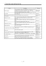
Electronic gear
The electronic gear is used to make adjustment so that the servo amplifier
setting matches the machine moving distance. Also, changing the
electronic gear value allows the machine to be moved at any multiplication
ratio to the moving distance using the servo amplifier.
Parameter No.
PA06, PA07
Auto tuning
Automatically adjusts the gain to optimum value if load applied to the servo
motor shaft varies.
Section 9.2
S-pattern acceleration/deceleration
time constant
Acceleration/deceleration can be made smoothly.
Parameters No.
PC13
Regenerative option
Used when the built-in regenerative resistor of the servo amplifier does not
have sufficient regenerative capability for the regenerative power
generated.
Section 14.2
Brake unit
Used when the regenerative option cannot provide enough regenerative
power.
Can be used with the servo amplifier of 5kW or more.
Section 14.3
Regeneration converter
Used when the regenerative option cannot provide enough regenerative
power.
Can be used with the servo amplifier of 5kW or more.
Section 14.4
Alarm history clear
Alarm history is cleared.
Parameter No.
PC18
I/O signal selection (Device setting)
Any input signal such as servo-on (SON) can be assigned to any pin of
CN6 connector.
Parameter No.
PD06 to PD08
PD12 PD14
Torque limit
Servo motor-torque is limited.
Section 4.6.3
Section 6.1.11
Output signal (DO) forced output
Output signal can be forced on/off independently of the servo status.
Use this function for output signal wiring check, etc.
Section 7.7.4
Section 8.5.7(4)
Test operation mode
JOG operation positioning operation DO forced output singl - step feed. Section 7.7
Section 8.5.7
Limit switch
The servo motor travel region can be limited using the forward rotation
stroke end (LSP)/reverse rotation stroke end (LSN).
Section 4.5.2
Software limit
The travel region is limited using parameters in terms of address.
The function similar to that of a limit switch is limited by parameter.
Section 6.3.6
Summary of Contents for MELSERVO MR-J3-xT
Page 22: ...8 MEMO ...
Page 156: ...4 46 4 SIGNALS AND WIRING MEMO ...
Page 276: ...7 26 7 MR Configurator MEMO ...
Page 324: ...10 16 10 SPECIAL ADJUSTMENT FUNCTIONS MEMO ...
Page 418: ...14 66 14 OPTIONS AND AUXILIARY EQUIPMENT MEMO ...

