3 - 52
3. CC-LINK COMMUNICATION FUNCTIONS
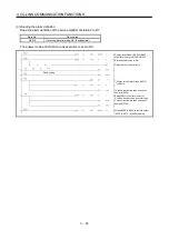
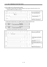
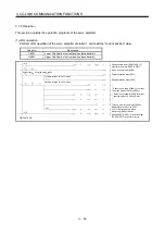
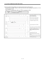
3.8 Continuous operation program example
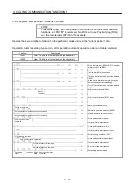
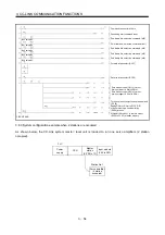
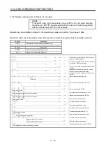
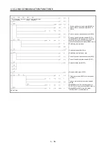
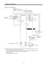
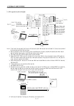
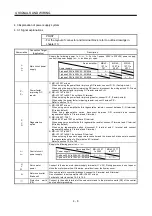
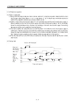
This section shows a program example which includes a series of communication operations from a servo
start. The program will be described on the basis of the equipment makeup shown in section 3.8.1, 3.8.3.
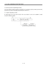
3.8.1 System configuration example when 1 station is occupied
As shown below, the CC-Link system master local unit is loaded to run one servo amplifier (1 station
occupied).
PLC
Power
supply
CPU
Master station
(X/Y00 to 1F)
Input module
(X30 to X3F)
Station No. 1
Servo amplifier
(1 station occupied)
Summary of Contents for MELSERVO MR-J3-xT
Page 22: ...8 MEMO ...
Page 156: ...4 46 4 SIGNALS AND WIRING MEMO ...
Page 276: ...7 26 7 MR Configurator MEMO ...
Page 324: ...10 16 10 SPECIAL ADJUSTMENT FUNCTIONS MEMO ...
Page 418: ...14 66 14 OPTIONS AND AUXILIARY EQUIPMENT MEMO ...


